
Bottom-bearing connection structure for external wall panels of assembled steel structure

A technology for connecting structures and steel structures, which is applied in the direction of walls, building components, building structures, etc. It can solve the problems of partial wall plate falling off, the durability of connecting parts, and the damage of connecting nodes, so as to reduce the seismic response and supporting effect of structures Ideal, effect of dissipating seismic energy

Pending Publication Date: 2017-06-20
安徽富煌建筑设计研究有限公司
View PDF4 Cites 13 Cited by
  • Summary
  • Abstract
  • Description
  • Claims
  • Application Information

AI Technical Summary

Problems solved by technology

However, under the action of an earthquake, the wall panels in this structure will jointly resist the horizontal shear force with the steel frame, and at the same time bear the wind load, and generate displacement to a certain extent, which will inevitably cause damage and destruction of the connecting nodes, resulting in the durability of the connecting parts. reduce, which in turn causes partial wall panels to fall off, and there is a certain degree of potential safety hazard

Method used


Image

  • Bottom-bearing connection structure for external wall panels of assembled steel structure
  • Bottom-bearing connection structure for external wall panels of assembled steel structure
  • Bottom-bearing connection structure for external wall panels of assembled steel structure

Examples


Embodiment Construction

[0032] In order to make the purpose, technical solutions and advantages of the embodiments of the present invention clearer, the technical solutions in the embodiments of the present invention will be clearly and completely described below in conjunction with the embodiments of the present invention. Obviously, the described embodiments are part of the present invention Examples, not all examples. Based on the embodiments of the present invention, all other embodiments obtained by persons of ordinary skill in the art without creative efforts fall within the protection scope of the present invention.

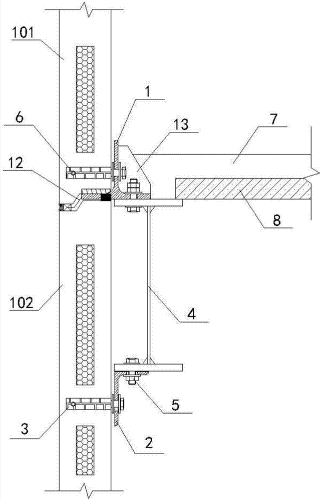
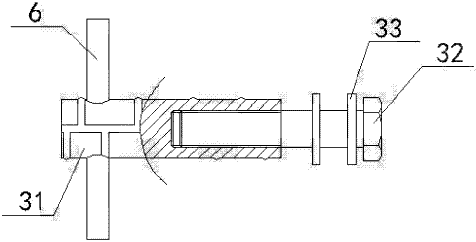
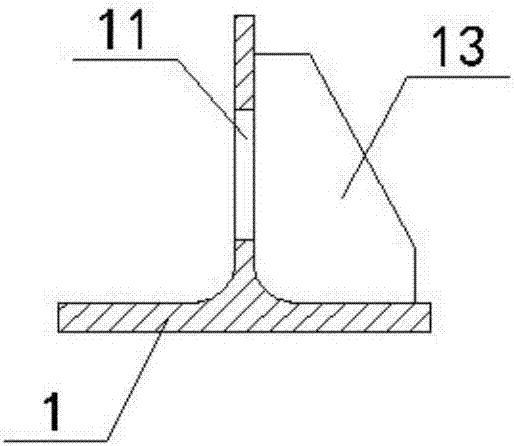
[0033] Such as Figure 1 to Figure 8 As shown, the structural relationship is: T-shaped steel 1 forms a vertical frictional sliding connection with the upper wall panel 101 through the connecting component 3, the angle steel 2 forms a vertical frictional sliding connection with the lower wall panel 102 through the connecting component 3, and the steel beam 4 The upper wing and t...


PUM

PropertyMeasurementUnit
Lengthaaaaaaaaaa

Abstract

The invention discloses a bottom-bearing connection structure for external wall panels of an assembled steel structure, and relates to the technical field of architectural structures. T-shaped steel and angle steel are slidably connected with an upper wall panel and a lower wall panel in a vertical friction mode through connecting components respectively, and the upper flange and the lower flange of a steel beam are slidably connected with the T-shaped steel and the angle steel in a horizontal friction mode through high-strength bolt groups respectively; the angle steel is suspended below the lower flange of the steel beam and conducts limiting adjustment of hanging and pulling on the upper wall panel, the T-shaped steel is located above the upper flange of the steel beam, the T-shaped steel extends into the seam of the wall panels, a steel plate above the seam is buried in advance, and the T-shaped steel is used for lifting the upper wall panel; composite floor slabs are anchored to the upper flange of the steel beam through welding studs and supported by the steel beam. According to the bottom-bearing connection structure for external wall panels of the assembled steel structure, the T-shaped steel is used for supporting the wall and bearing the weight of the wall, which is in good accordance with a wall panel bottom-bearing force model. Under the action of an earthquake, the connecting components and the high-strength bolt groups can relatively slide in the vertical holes and horizontal holes of the T-shaped steel and the angle steel, consuming and loading energy to protect the wall panels, and achieving the functions of dissipating the earthquake energy and reducing structural earthquake responses.

Description

technical field [0001] The invention relates to the technical field of building structures, in particular to a connection structure for an externally hung wall panel of an assembled steel structure. Background technique [0002] Assembled steel structure is a common structural system in modern buildings. Its structural components are transported to the site after being processed in the factory, and are connected by high-strength bolts and welding. It has the advantages of less on-site workload, fast construction speed, and light weight. The function of small earthquake action. Each process on the construction site can be operated in a three-dimensional manner, which further improves construction efficiency and shortens the construction period. [0003] Composite wall panels are widely used in steel structure residential systems. Compared with ordinary wall materials, composite wall panels have the advantages of high bearing capacity, good thermal insulation and sound insul...

Claims


Application Information

Patent Timeline
IPC IPC(8): E04B2/56
CPCE04B2/56
Inventor 沈万玉田朋飞王从章童敏崔海龙
Owner 安徽富煌建筑设计研究有限公司
Learn More