
Assembly channel steel punching beam column joint connecting device capable of achieving function recovery

A node connection and recovery function technology, applied in the direction of building components, floors, buildings, etc., can solve the problems that the quality of welds cannot be guaranteed, cannot achieve rapid recovery, and is prone to brittle fracture, so as to achieve convenient and fast fastening work. The effect of improving ductility and turning ability and reducing construction difficulty

Inactive Publication Date: 2017-06-20
BEIJING UNIV OF TECH
View PDF5 Cites 39 Cited by
  • Summary
  • Abstract
  • Description
  • Claims
  • Application Information

AI Technical Summary

Problems solved by technology

The existing beam-column joints mainly have the following disadvantages: ①The beam-column connection mostly adopts the connection form of on-site welding, the quality of the weld cannot be guaranteed, and the weld at the beam-column joint is prone to brittle fracture under earthquake action; ②In the column Most of the ends are strengthened by adding splicing plates or adding haunches, and multiple welds are superimposed, and the stress generated is more complicated
③The installation and disassembly process of prefabricated steel structure buildings can realize full assembly, but in terms of post-earthquake repair, it is no different from traditional steel structure buildings, and cannot realize "prefabricated with rapid recovery function"

Method used


Image

  • Assembly channel steel punching beam column joint connecting device capable of achieving function recovery
  • Assembly channel steel punching beam column joint connecting device capable of achieving function recovery
  • Assembly channel steel punching beam column joint connecting device capable of achieving function recovery

Examples


Embodiment Construction

[0032] Below in conjunction with accompanying drawing, the embodiment of this patent is described in detail.

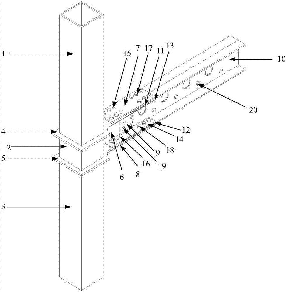
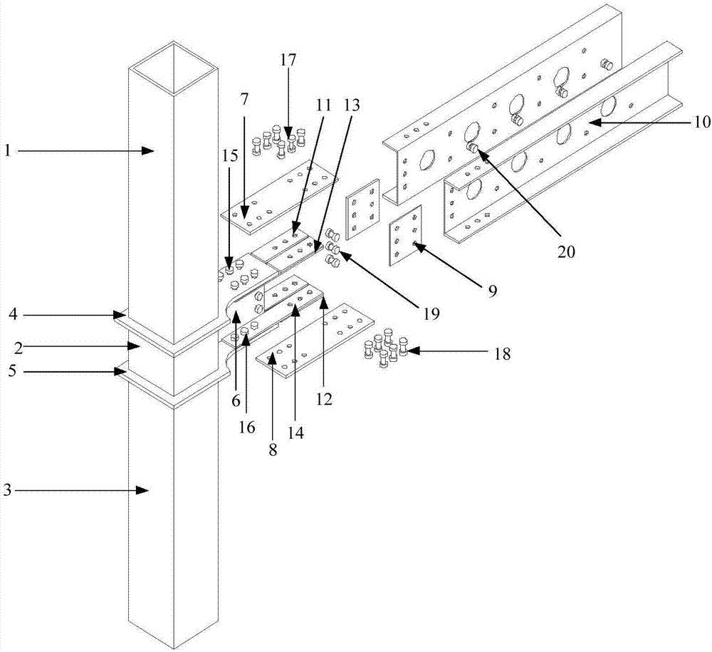
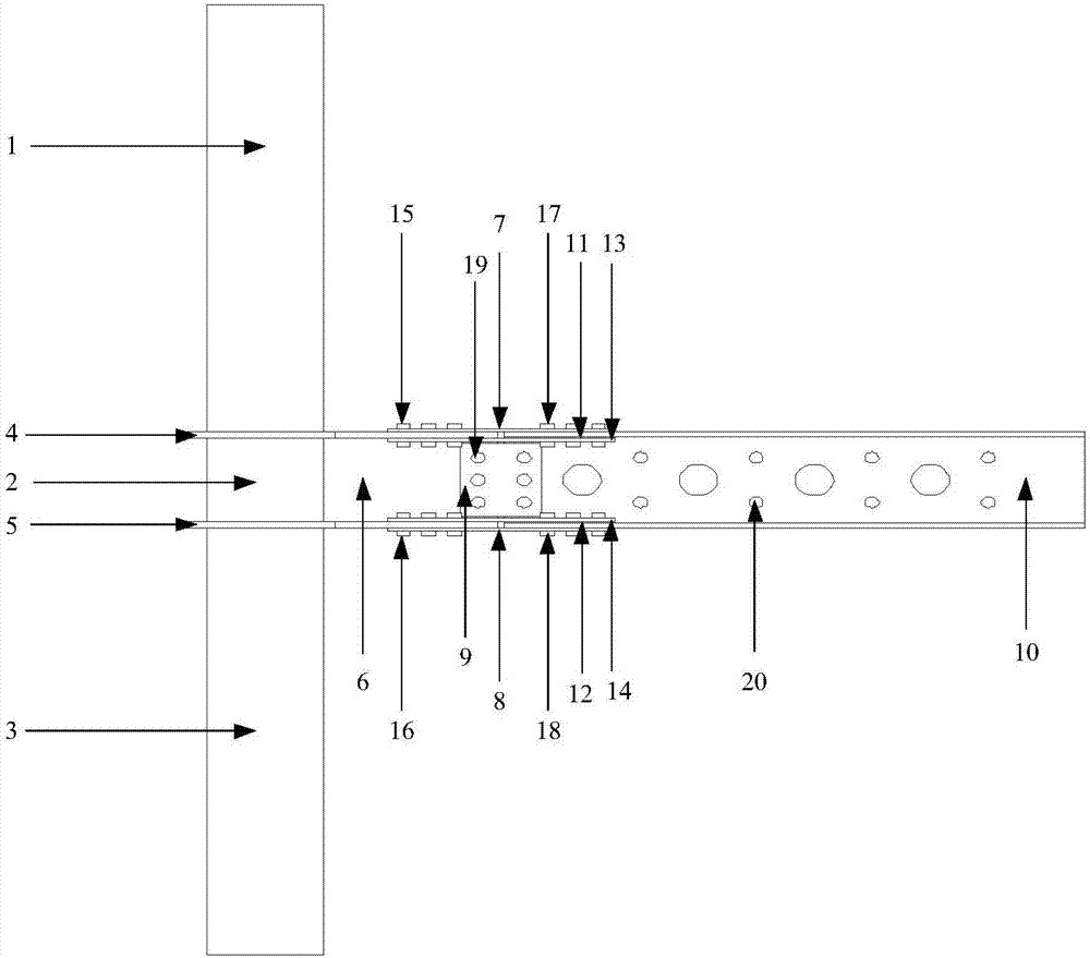
[0033] Such as Figure 1-5 As shown, a prefabricated channel steel opening beam-column node connection device with recoverable function includes the following components:

[0034] 1——The upper steel pipe column;

[0035] 2——Chinese steel pipe column;

[0036] 3——The lower steel pipe column;

[0037] 4 - the upper square partition;

[0038] 5——The lower square partition;

[0039] 6——web plate of cantilever beam section;

[0040] 7——The connecting plate on the upper flange;

[0041]8——The lower connecting plate of the lower flange;

[0042] 9——web shear plate;

[0043] 10——channel steel opening beam;

[0044] 11——upper flange backing plate;

[0045] 12——The backing plate of the lower flange;

[0046] 13——The lower connecting plate of the upper flange;

[0047] 14 - connecting plate on the lower flange;

[0048] 15——the first bolt group;

[0049] 16——the se...


PUM


Abstract

The invention relates to an assembly channel steel punching beam column joint connecting device capable of achieving function recovery and belongs to the field of structural engineering. The assembly channel steel punching beam column joint connecting device capable of achieving function recovery is composed of a square steel pipe column with a cantilever beam section, a channel steel punching beam section and a connecting device of the cantilever beam section and the channel punch beam section. All welding parts of the joint connection device are all finished in a factory, so that precision and quality of welds are easier to control. Construction speed is greatly increased and construction quality is greatly improved, and a spatial structure of the channel punch beam section of the channel is conducive to pipeline penetration; the channel steel punching beam and a floor can be assembled and molded in the factory to form modular assembly units. Then all the modular assembly unit and the square steel pipe column with the cantilever beam section achieve assembly connection through the channel steel punching beam. Joints of the connection device can be used for both of beam end reinforcing and cover plate connection weakening. A multi-energy dissipation mechanism can be realized, a plastic hinge is transferred to a cover plate and a connecting plate. The function of structures can be recovered only by replacing the connecting plate after an earthquake.

Description

technical field [0001] The patent relates to a reversible assembled channel steel opening beam-column node connection device, which belongs to the technical field of structural engineering. Background technique [0002] The prefabricated building system has significant advantages such as short design and manufacturing cycle, integrated design and production, low labor intensity, high production efficiency, energy saving and comprehensive economic benefits, etc. It has become an important building and housing form in developed countries such as Europe, America, Japan and Australia. . [0003] Following the Northridge Earthquake and the Hanshin Earthquake, extensive and in-depth studies have been conducted on the failure causes of beam-column welded rigid joints, and various measures to improve the seismic performance of beam-column joints have been proposed. It can be mainly divided into two types: improving the weld performance of beam-column joints and moving the plastic h...

Claims


Application Information

Patent Timeline
Patent Type & Authority Applications(China)
IPC IPC(8): E04B1/24E04B1/58E04B5/14
CPCE04B1/2403E04B5/14E04B2001/2415E04B2001/2418E04B2001/2454E04B2001/2457E04B2001/2466E04B2001/2484
Inventor 姜子钦王琦张爱林李世欢方浩
Owner BEIJING UNIV OF TECH
Learn More