A working electrolytic chamber device with temperature control

A technology of temperature control and electrolysis chamber, applied in the direction of electrolysis components, electrolysis process, cells, etc., can solve the problems of low control precision, difficult fixation, and many faults, and achieve the effect of simple device structure, easy temperature control, and simple operation

Active Publication Date: 2018-09-21
GUIZHOU UNIV
View PDF8 Cites 0 Cited by
  • Summary
  • Abstract
  • Description
  • Claims
  • Application Information

AI Technical Summary

Problems solved by technology

[0003] The technical problem to be solved by the present invention is: to provide a working electrolytic chamber device with temperature control, using a working electrolytic chamber device with temperature control to solve the problem of existing electrodeposition equipment, electrolytic cell single-layer glass material or hollow glass material , the common practice of single-layer glass electrolytic cells is to put the anode electrodeposition cell device into a water bath or hollow glass and fill it with hot water to control the temperature. The water bath or oil bath has no magnetic stirring function, so some chemical reactions are easily affected by diffusion control, thus affecting the electrolytic deposition effect. In addition, the insulating glass electrodeposition device is filled with temperature-controlled circulating water, but it can The temperature control circulating water device is complicated, there are many faults, and the control accuracy is not high

Method used


Image

  • A working electrolytic chamber device with temperature control
  • A working electrolytic chamber device with temperature control
  • A working electrolytic chamber device with temperature control

Examples


Embodiment Construction

[0027] The invention will be further introduced below in conjunction with the accompanying drawings and specific embodiments.

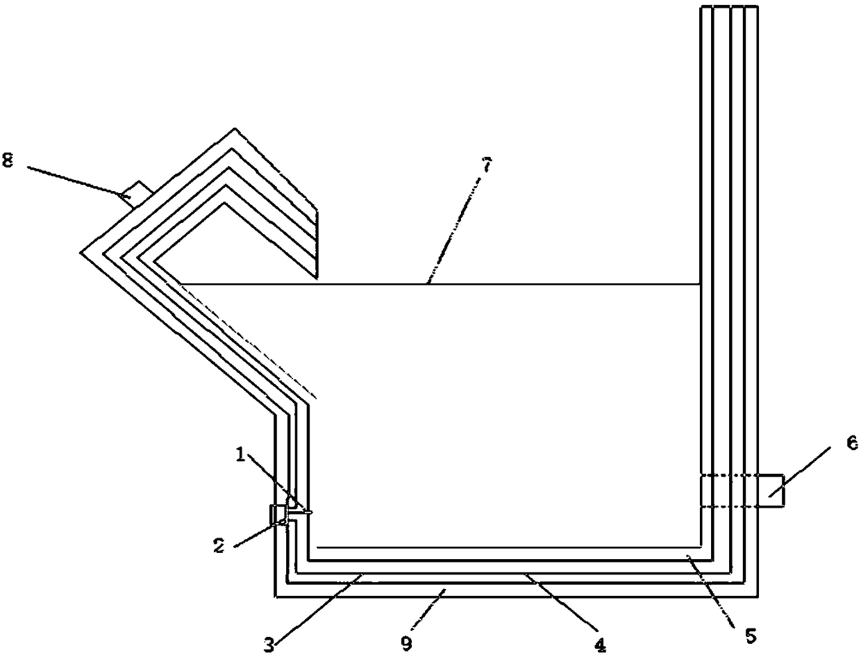
[0028] Such as Figure 1~5 As shown, a working electrolytic chamber device with temperature control includes temperature sensor 1, electrical component installation hole 2, heating resistor 3, interlayer one 4, interlayer two 5, auxiliary electrode pool interface 6, electrolyte solution 7, measuring electrode installation Hole 8, interlayer three 9, the working electrolysis chamber has interlayer one 4, interlayer two 5, interlayer three 9, electrical component installation hole 2, auxiliary electrode pool interface 6 and measuring electrode installation hole 8; described interlayer one 4 There is a heating resistor 3 inside, the interlayer 2 5 is filled with a heat transfer medium and a temperature sensor 1 is installed, and the interlayer 3 9 is filled with heat insulating material.

[0029] Further work, the inner wall of the electrolytic chamber ...


PUM


Abstract

The invention discloses a temperature control type working electrolyzing chamber device. The device comprises a working electrolyzing chamber, a temperature control unit and a temperature detecting unit, wherein the working electrolyzing chamber is provided with a first interlayer, a second interlayer, a third interlayer, an electrical element mounting hole, an auxiliary electrolytic cell interface and a measuring electrode mounting hole; a heating resistor is arranged in the first interlayer; the second interlayer is filled with heat transferring medium and is provided with a temperature sensor; the third interlayer is filled with heat insulation materials. With the adoption of the temperature control type working electrolyzing chamber device, the problems of an existing electro-deposition device that the electrolytic cell is manufactured through single-layer glass or hollow glass, the electrolytic cell manufactured through the single-layer glass generally works as that an anodic electrodeposition cell device is arranged into a water bath kettle or the hollow glass is filled with hot water, and the temperature is controlled; the anodic electrodeposition cell device is hardly fixed in the water bath kettle or an oil bath kettle, and some water bath kettle or oil bath kettle is free from magnetic stirring function, and thus some chemical reaction is easily influenced by dispersing control, can be solved.

Description

technical field [0001] The invention relates to a working electrolysis chamber device, in particular to a working electrolysis chamber device with temperature control, belonging to the field of electrochemistry. Background technique [0002] Existing electrodeposition equipment, the electrolytic cell is made of single-layer glass or insulating glass, and the usual method for the electrolytic cell made of single-layer glass is to put the anode electrodeposition cell device into a water bath or fill the inside of the insulating glass with hot water to control the temperature. It is not easy to fix the anode electrodeposition device in a water bath or oil bath, and some water baths or oil baths have no magnetic stirring function, which makes certain chemical reactions easily affected by diffusion control, thereby affecting the effect of electrolytic deposition. In addition, the electrolytic deposition of insulating glass In the deposition device, the hollow glass is filled with...

Claims


Application Information

Patent Timeline
Patent Type & Authority Patents(China)
IPC IPC(8): C25D17/02C25D21/02C25D21/12
CPCC25D17/02C25D21/02C25D21/12
Inventor 王扬张靖何宇施雅陈澎
Owner GUIZHOU UNIV
Why Eureka
Try Eureka