Pneumatic muscle upper limb assistance exoskeleton system

A pneumatic muscle and exoskeleton technology, applied in the direction of artificial arms, manipulators, program-controlled manipulators, etc., can solve the problems of low efficiency-to-mass ratio, high energy consumption, and high processing requirements, and achieve good collaboration and reduce processing costs.

Pending Publication Date: 2017-06-20
彭爽
View PDF6 Cites 5 Cited by
  • Summary
  • Abstract
  • Description
  • Claims
  • Application Information

AI Technical Summary

Problems solved by technology

The advantages of the motor drive system are high efficiency, precise control, and easy installation, but its low efficiency-to-mass ratio makes it difficult to achieve wide-scale use in exoskeletons
The advantage of the hydraulic system is that it has a large power-to-mass ratio and can generate large thrust in a small volume; however, the hydraulic system uses hydraulic oil as the working medium, which is prone to leakage problems; and the hydraulic drive system has low efficiency and consumes a lot of energy. High requirements, high processing requirements, high cost
The pneumatic system has the advantages of clean working medium, high efficiency, light weight, and low cost, but it is difficult to apply to high-power systems due to the low power-to-mass ratio of cylinder components

Method used


Image

  • Pneumatic muscle upper limb assistance exoskeleton system
  • Pneumatic muscle upper limb assistance exoskeleton system
  • Pneumatic muscle upper limb assistance exoskeleton system

Examples


Embodiment Construction

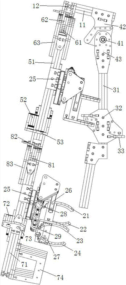
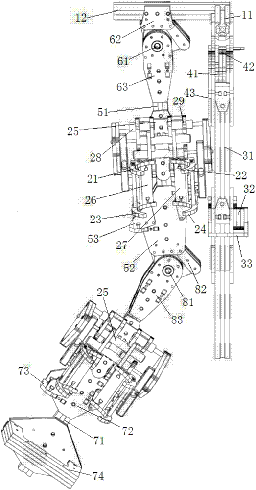
[0022] refer to Figure 1 to Figure 3 , Figure 1 to Figure 3 It is a structural schematic diagram of a specific embodiment of the present invention.

[0023] Such as Figure 1 to Figure 3 As shown, a pneumatic muscle upper limb assisted exoskeleton system includes a dorsal arm bone installed on the back of the human body and cooperating with the human body back, an upper arm bone installed on the upper arm of the human body and cooperating with the upper arm of the human body, an The forearm bone for the coordinated movement of the forearm also includes a shoulder bone for connecting the back arm bone and the upper arm bone; the shoulder bone includes a shoulder lateral skeleton 11 and a shoulder forward skeleton 12, and the shoulder bone The shoulder side frame 11 and the shoulder forward frame 12 are combined into an L-shaped structure; the shoulder side frame 11 is provided with a first joint module below the shoulder frame 12, and the shoulder forward frame 12 is provid...


PUM


Abstract

The invention discloses a pneumatic muscle upper limb assistance exoskeleton system which comprises a back arm bone, an upper arm bone, a front arm bone, a shoulder side direction skeleton and a shoulder front direction skeleton. The upper end of the back arm bone is connected with the shoulder side direction skeleton through a first joint module, and the back arm bone is connected with the shoulder side direction skeleton through a pneumatic muscle used for driving the first joint module to move; the upper end of the upper arm bone is connected with the shoulder front direction skeleton through a second joint module, and the upper arm bone is connected with the shoulder front direction skeleton through a pneumatic muscle used for driving the second joint module to move; the front arm bone is connected with the upper arm bone through a third joint module, and the front arm bone is connected with the upper arm bone through a pneumatic muscle used for driving the third joint module to move; and the upper arm bone and the front arm bone are each provided with a pressing ring. According to the pneumatic muscle upper limb assistance exoskeleton system, the pneumatic muscles are adopted as execution elements, and a user and the exoskeleton system have good interoperability.

Description

technical field [0001] The invention relates to the technical field of mechanical exoskeleton products, in particular to a pneumatic muscle upper limb assisted exoskeleton system. Background technique [0002] Mechanical exoskeletons are human-oriented robots, which can be defined as those devices worn by users that supplement or replace limbs. An exoskeleton can be steered on one side of the user's limb, coordinating movement with the user's limbs, or replace a part of a disabled user's limb and cooperate with the remaining limbs; but this does not necessarily mean that the exoskeleton must be Movable or portable, a large part of the reason is the limitation of the volume and weight of actuators and power sources; mechanical exoskeleton can be regarded as a technology that enhances, adapts, and protects the wearer's body. The exoskeleton can expand the user's ability on the basis of the user's manipulation, helping the user achieve strength beyond his own; it can also help...

Claims


Application Information

Patent Timeline
Patent Type & Authority Applications(China)
IPC IPC(8): B25J9/00A61F2/54A61F2/58
CPCA61F2/54A61F2/581B25J9/0006A61F2002/543A61F2002/546
Inventor 彭爽
Owner 彭爽
Why Eureka
Try Eureka