
Disassembly and assembly device special for piston and connecting rod unit of automobile engine and using method

An automobile engine, piston connecting rod technology, applied in hand-held tools, manufacturing tools and other directions, can solve the problems of difficulty in taking out the piston and connecting rod group, low disassembly and assembly efficiency, and narrow position, and achieves good promotion and application value. The effect of reducing maintenance time and labor intensity

Inactive Publication Date: 2017-06-20
GUANGDONG GUANGDONG SHAOGANG ENG TECH
View PDF5 Cites 4 Cited by
  • Summary
  • Abstract
  • Description
  • Claims
  • Application Information

AI Technical Summary

Problems solved by technology

[0002] The piston and connecting rod group are the key components of the engine operation. Generally, multiple pistons and connecting rod assemblies are connected with the crank-and-rod mechanism in different engines. A single piston and connecting rod assembly weighs about 10-12 kg. It is very difficult to take out the connecting rod group and the connecting rod group from the combustion chamber space of the engine. Firstly, the upper cover of the engine cylinder and the oil pan must be opened completely, and after the connecting rod screw fixing the connecting rod cover and the connecting rod under the engine are removed, use a wooden stick or a hand Go in and push up from the bottom of the car, and push the piston and connecting rod assembly upwards out of the combustion chamber. Inside the cylinder, there are parts such as the crankshaft. In the process of disassembly and installation, two people must coordinate their efforts, and the efficiency of disassembly and assembly is low

Method used


Image

  • Disassembly and assembly device special for piston and connecting rod unit of automobile engine and using method
  • Disassembly and assembly device special for piston and connecting rod unit of automobile engine and using method
  • Disassembly and assembly device special for piston and connecting rod unit of automobile engine and using method

Examples


Embodiment Construction

[0023] The present invention will be further described below in conjunction with the accompanying drawings and embodiments.

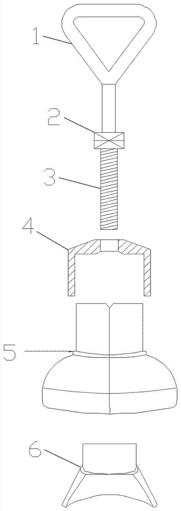
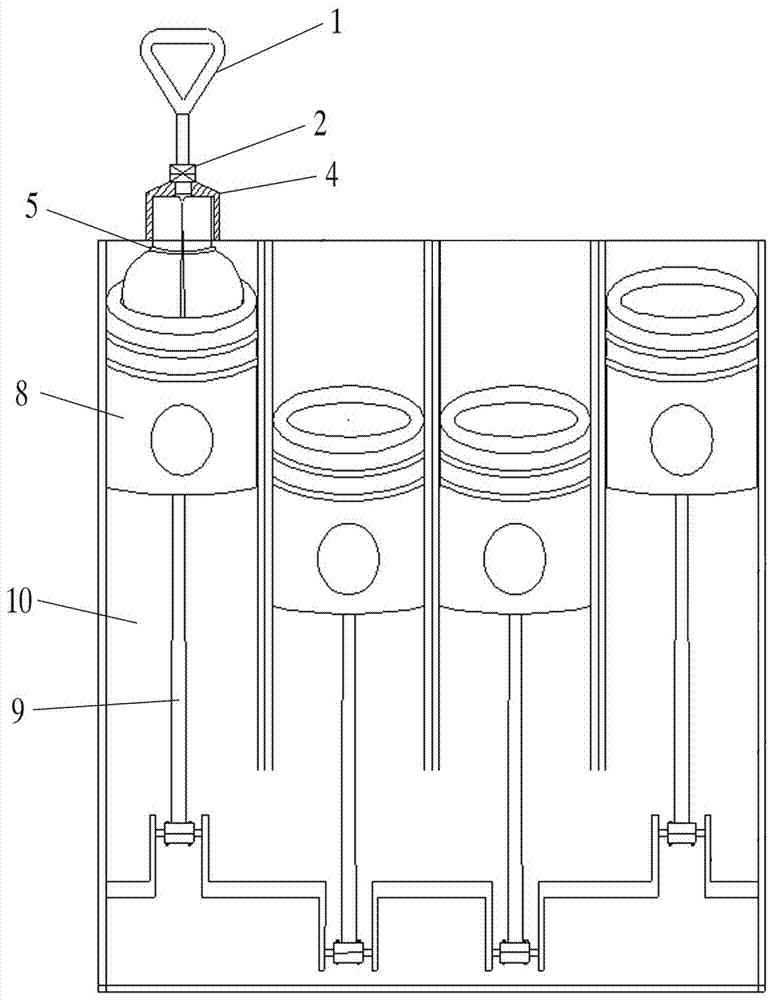
[0024] see Figure 1-Figure 3 , a special disassembly and assembly device for the piston connecting rod group of an automobile engine, which consists of a pull ring 1, a screw rod 2, a fastening bolt 3, a cage 4, a left and right movable wedge 5 and a fastening wedge 6, which are sequentially connected from top to bottom. According to the structure of the piston 8 and the size of the combustion chamber 10, the left and right movable wedges 5 of different diameters are selected and placed in the groove 7 on the top of the piston 8, and after they are tightened, the 9 groups of connecting rods of the piston 8 are pulled out or installed into the engine.

[0025] The hole diameter of the pull ring 1 is 60mm.

[0026] The size of the screw 2 is ¢10mm*40mm.

[0027] The size of the fastening bolt 3 is ¢10mm*50mm.

[0028] The cage 4 has an outer diamet...


PUM


Abstract

The invention relates to a disassembly and assembly device special for a piston and connecting rod unit of an automobile engine and a using method. The device is formed by sequentially and fixedly connecting a pull ring, a screw rod, a fastening bolt, a retainer, left and right movable wedge blocks and a fastening wedge from top to bottom. According to the different structures of pistons and the different sizes of combustion chambers, the left and right movable wedge blocks with different diameters are selected to be placed in grooves in the tops of the pistons and fastened, and then the piston and connecting rod unit is pulled out or installed into the engine. The disassembly and assembly device is applicable to disassembling and assembling pistons and connecting rods of engines of different types of automobiles, and has the advantages of being safe, efficient, easy to operate, good in using effect and the like.

Description

technical field [0001] The invention belongs to the technical field of equipment maintenance, and relates to a special assembly and disassembly device for a piston connecting rod group of an automobile engine and a using method, and is especially suitable for the maintenance of crank connecting rod mechanisms of automobiles and crane engines. Background technique [0002] The piston and connecting rod group are the key components of the engine operation. Generally, multiple pistons and connecting rod assemblies are connected with the crank-and-rod mechanism in different engines. A single piston and connecting rod assembly weighs about 10-12 kg. It is very difficult to take out the connecting rod group and the connecting rod group from the combustion chamber space of the engine. Firstly, the upper cover of the engine cylinder and the oil pan must be opened completely, and after the connecting rod screw fixing the connecting rod cover and the connecting rod under the engine are...

Claims


Application Information

Patent Timeline
Patent Type & Authority Applications(China)
IPC IPC(8): B25B27/02
CPCB25B27/02B25B27/0035
Inventor 刘力忠张鑫钟然智赵佳祥郑祖光陈铭初刘志军李俊龙刘永治朱春波胡晓宇彭寿开邓志强汤志勇王强陈涛罗尧圣王小弟
Owner GUANGDONG GUANGDONG SHAOGANG ENG TECH
Learn More