Forging hammer

A technology of structure and device, applied in the direction of hammer, forging/pressing/hammer device, power hammer, etc., can solve the problems of high load of hammer driver and limit the life of hammer driver, etc.

Active Publication Date: 2017-06-20
SCHULER PRESSEN GMBH & CO KG
View PDF6 Cites 0 Cited by
  • Summary
  • Abstract
  • Description
  • Claims
  • Application Information

AI Technical Summary

Problems solved by technology

[0003] It is problematic in the operation of such known forging hammers that the hammer drive is subjected to very high loads, which on the one hand severely limits the life of the hammer drive

Method used


Image

  • Forging hammer
  • Forging hammer
  • Forging hammer

Examples


Embodiment Construction

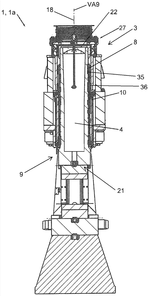
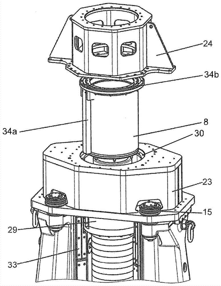
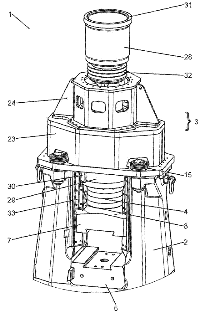
[0117] figure 1 A perspective illustration of the forging hammer 1 is shown. The forging hammer comprises an anvil 2 which has a U-like profile. A head section 3 is arranged on the anvil 2 . In the exemplary embodiment shown, the head section 3 is composed of a lower head section 23 and an upper head section 24 .

[0118] In a manner not shown further, the header section 3 can also be designed in one piece.

[0119] A cover 16 is arranged on the head section 3 or on the upper head section 24 . A striker 4 is formed in the anvil 2 . The forging hammer 1 comprises an upper part 7 of a forging die 6 and a lower part 5 of the forging die 6 for machining a workpiece (not shown).

[0120] exist figure 2 is shown in schematic side view already in figure 1 The forging hammer 1 shown in. The forging hammer 1 is here designed as a short-stroke die hammer. The forging hammer 1 comprises the mentioned anvil 2 , an anvil insert 14 , a head section 3 and a runner 9 with a hammer h...


PUM


Abstract

The invention relates to a forging hammer (301) comprising a frame (313), a stator (308) and a mover (309), wherein the frame (313) comprises an anvil (302) and a head section (303), wherein , the stator (308) is arranged at the frame (313), wherein the mover (309) includes a hammerhead (304) and a secondary part (335), wherein the secondary part (335) includes at least one magnet device (1701 ), and wherein the mover (309) is guided in the anvil (302). At least one damping device ( 1702 ) and/or at least one adjusting device ( 1703 ) is arranged between the stator ( 308 ) and the head section ( 303 ).

Description

technical field [0001] The invention relates to a forging hammer according to the preamble of claim 1 . Background technique [0002] Forging hammers for use in industry, for example in free-form forging or in die forging, are sufficiently known from the prior art. A detailed introduction about this specialized field can be found in the document "Handbook Retrofit Technology", Eckhart Doege, Bernd-Arno Behrens, Springer Verlag, 2nd edition, 2010, pages 719 and subsequent pages (Literatur "Handbuch Umformtechnik”, Eckhart Doege, Bernd-Arno Behrens, Springer-Verlag, 2. Auflage, 2010, Seiten 719 ff.). [0003] The problem with operating such known forging hammers is that the hammer drive is exposed to very high loads, which on the one hand severely limits the life of the hammer drive. On the other hand, when using forging hammers which are driven by means of a linear motor and are referred to as linear hammers, a precise alignment of the stator and mover is absolutely necessa...

Claims


Application Information

Patent Timeline
Patent Type & Authority Applications(China)
IPC IPC(8): B21J7/02B21J7/20
CPCB21J7/30B21J7/04B21J7/02B21J7/20
Inventor A.德雷赫尔M.比格G.韦格尔
Owner SCHULER PRESSEN GMBH & CO KG
Why Eureka
Try Eureka