
Beverage ingredient container achieving stable-pressure outputting

A technology for beverage ingredients and stabilized output, applied in beverage preparation devices, household appliances, applications, etc., can solve problems such as pollution, reduced beverage taste, and easy splashing of beverages out of the cup, so as to prolong the dissolution time, improve the taste, and avoid problems. The effect of wasted beverages

Active Publication Date: 2017-06-20
SHENZHEN DINGJIA HONGSI BEVERAGE TECH CO LTD
View PDF11 Cites 3 Cited by
  • Summary
  • Abstract
  • Description
  • Claims
  • Application Information

AI Technical Summary

Problems solved by technology

[0003] The invention provides a beverage ingredient container with stable voltage output, which is used to overcome the problem that the existing beverage ingredient container cannot achieve stable voltage output, the taste of the drink is reduced, repeated use is easy to cause pollution, and the outflowing drink is easy to splash out of the cup. technical problem

Method used


Image

  • Beverage ingredient container achieving stable-pressure outputting
  • Beverage ingredient container achieving stable-pressure outputting
  • Beverage ingredient container achieving stable-pressure outputting

Examples


Embodiment 1

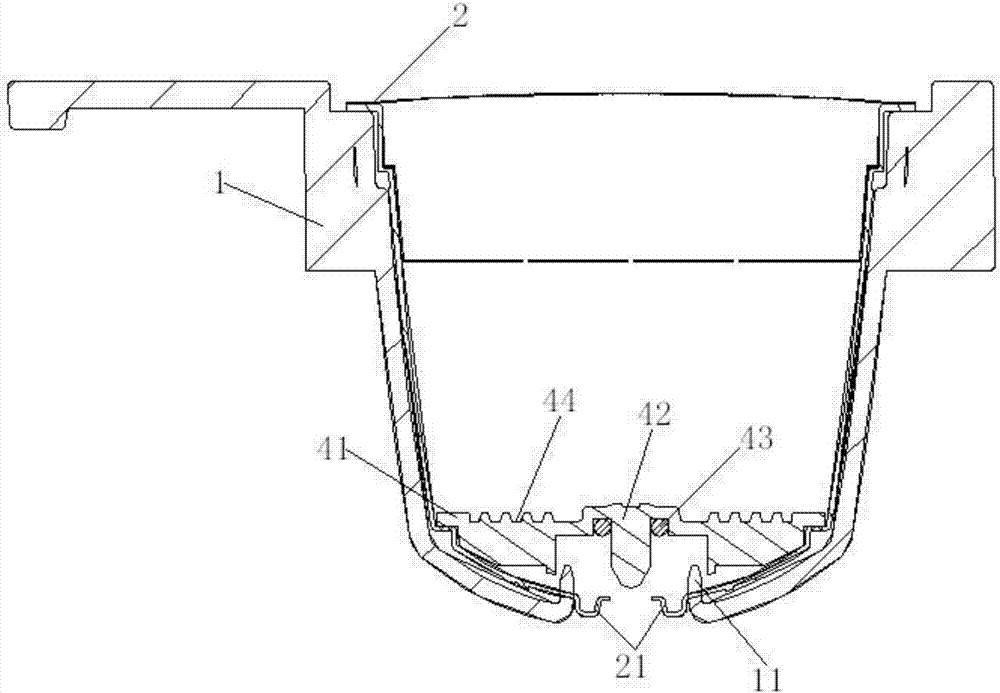
[0029] like figure 2 As shown, the micro-filter reverse pressure device 4 includes a filter disc 41, the surface of the filter disc 41 is provided with a diversion groove 44, the middle bottom of the filter disc 41 is provided with a shaft post 42, and the filter disc 41 is surrounded by a shaft post 42. As for the pores, a rubber ring 43 is sheathed on the surface of the shaft column 42 , and the rubber ring 43 is used to close the pores around the shaft column 42 . The diversion groove 44 is centered on the shaft column 42, and is annularly arranged on the surface of the filter disc 41. The diversion groove 44 includes a multi-layer structure, and the middle part of the diversion groove 44 is also provided with a water flow groove. This layer-by-layer diversion structure, in The vortex is caused by the washing of water pressure, thus accelerating the dissolution of powder.

[0030] In this embodiment, the hole is set on the top of the filter plate 41, and the rubber ring 4...

Embodiment 2

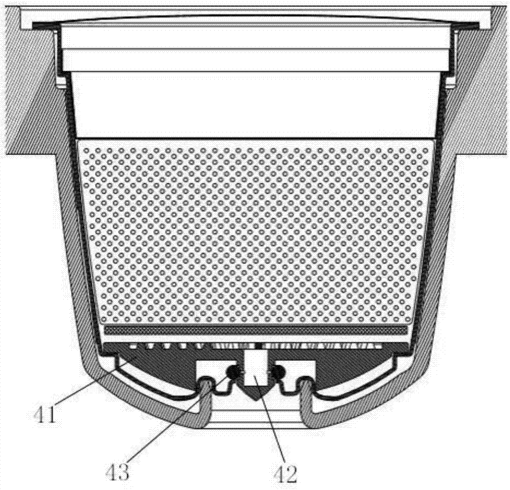
[0038] like image 3 As shown, the micro-filter reverse pressure device 4 includes a filter disc 41, the surface of the filter disc 41 is provided with a guide groove 44, the middle bottom of the filter disc 41 is provided with a shaft column 42, and a rubber ring 43 is sleeved on the surface of the shaft column 42, The rubber ring 43 is used to close the pores around the shaft column 42 . The diversion groove 44 is centered on the shaft column 42, and is annularly arranged on the surface of the filter disc 41. The diversion groove 44 includes a multi-layer structure, and the middle part of the diversion groove 44 is also provided with a water flow groove. This layer-by-layer diversion structure, in The vortex is caused by the washing of water pressure, thus accelerating the dissolution of powder.

[0039] In this embodiment, the pores are opened on both sides of the shaft column 42, and the rubber ring 43 is sleeved on the outer surface of the hole. The shaft column adopts a h...


PUM


Abstract

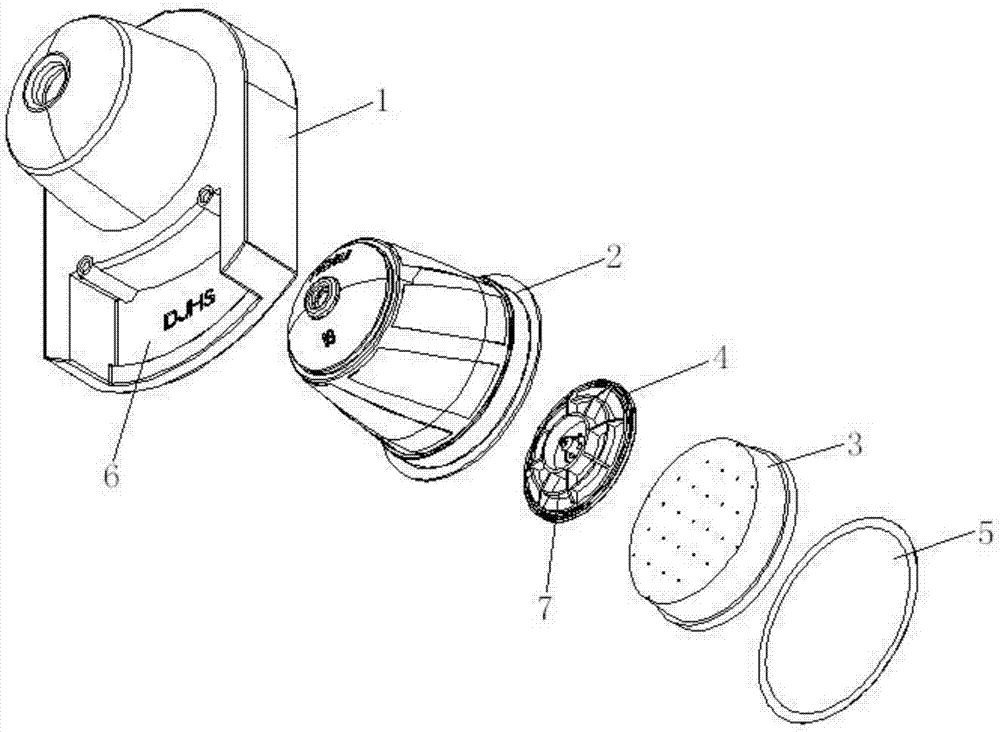
The invention discloses a beverage ingredient container achieving stable-pressure outputting. The beverage ingredient container comprises an external retainer and a heat-resistant container arranged in a cavity of the external retainer, and a micro filtering divider and a micro filtering transformer are installed in a cavity of the heat-resistant container; the micro filtering transformer comprises a filtering plate, flow guide grooves are formed in the surface of the filtering plate, an axial column is arranged at the bottom of the middle of the filtering plate, pores are formed at the periphery of the axial column, and the bottom of the axial column is sleeved with a rubber ring; a circular hole is formed in the bottom of the middle of the external retainer, the inner wall of the circular hole is upwards flanged to form a protrusion, a cup-shaped structure with an upward opening is arranged at the bottom of the heat-resistant container, the protrusion is connected with the cup-shaped structure in an abutting mode, and a buffer space is formed over the cup-shaped structure. Accordingly, stable-pressure outputting of a beverage in the beverage ingredient container is achieved, the mouthfeel of the beverage is improved, contamination generated in the using process is completely eradicated, and the flow-out beverage cannot splash.

Description

technical field [0001] The invention relates to the technical field of a container for storing beverage ingredients and coffee capsules, in particular to a beverage ingredient container with a stable pressure output. Background technique [0002] A beverage ingredient container is a device for preparing beverages by injecting a stream of pressurized water into the beverage ingredient container. With the development of the coffee industry, various coffee packaging and brewing devices have emerged, such as coffee capsules and coffee capsule machines for brewing coffee capsules, coffee pods and coffee pod machines for brewing coffee pods, producing coffee capsules and There are many machine manufacturers on the market. This type of coffee capsule and coffee capsule machine brings great convenience to people for brewing coffee, but there are also some disadvantages at the same time. When the existing coffee capsule product is brewed, after a water flow is pressurized, the coffe...

Claims


Application Information

Patent Timeline
IPC IPC(8): A47J31/41A47J31/06A47J31/46
CPCA47J31/0615A47J31/41A47J31/467
Inventor 梅洋唐鸣
Owner SHENZHEN DINGJIA HONGSI BEVERAGE TECH CO LTD
Learn More