Broadband arbitrary-power-ratio waveguide power divider
A power division ratio and waveguide technology, applied in the microwave field, can solve problems such as the deterioration of the amplitude flatness of the branch of the power splitter, limit the use range of the waveguide power splitter, and reduce the bandwidth, etc., to achieve increased bandwidth, simple structure, and easy processing Effect
- Summary
- Abstract
- Description
- Claims
- Application Information
AI Technical Summary
Problems solved by technology
Method used
Image

Examples
Embodiment 1
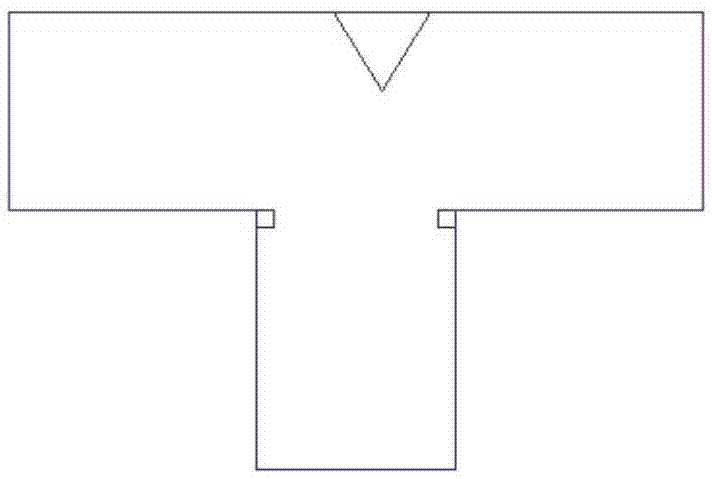
[0041] Such as image 3 , Figure 5 , Figure 7 and Figure 8 As shown, the width of the rectangular waveguide 1, the rectangular waveguide 2 of the left branch, and the rectangular waveguide 3 of the right branch are all 22.86mm in width and 10.16mm in height; when the power distribution ratio of the left and right branches is 2:1, and The length and width of the metal body 4 on the left side of the road and the metal body on the right side of the road are both 1.8mm, and the height is 10.16mm; The centerline of the Helu rectangular waveguide 1 is 5.5mm; the right branch metal body 6 is a cuboid with a length of 11.6mm, a width of 1mm, and a height of 10.16mm, and the distance from the centerline of the Helu rectangular waveguide 1 is 1.8mm. From Figure 7 and Figure 8 It can be seen from the simulation results that the S11 parameter is less than -15dB in the frequency range of 8GHz to 11.7GHz, less than -20dB in the frequency range of 8.5GHz to 10.5GHz, and the power a...
Embodiment 2
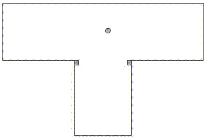
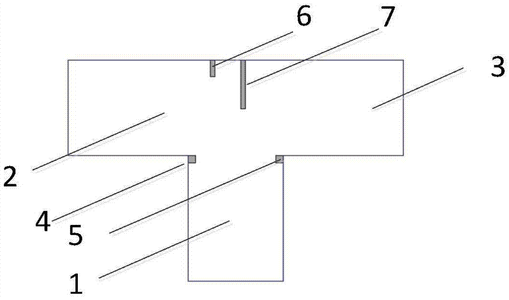
[0043] Such as Figure 4 , Figure 6 , Figure 9 and Figure 10 As shown, the width of the rectangular waveguide 1, the rectangular waveguide 2 of the left branch, and the rectangular waveguide 3 of the right branch are all 22.86mm in width and 10.16mm in height; when the power distribution ratio of the left and right branches is 2:1, and The length and width of the metal body 4 on the left side of the road and the metal body 5 on the right side of the road are both 1.8mm and 10.16mm in height; the metal body 6 in the left branch is a cylinder with a radius of 0.8mm and a height of 10.16mm. The centerline of waveguide 1 is 3.5mm, and the distance to the side of left branch rectangular waveguide 2 far away from Helu rectangular waveguide 1 is 3.5mm; the right branch metal body 7 is a cylinder with a radius of 0.8mm and a height of 10.16mm. The centerline of the sum-way rectangular waveguide 1 is 2.4 mm, and the distance from the side of the right-way rectangular waveguide 3 ...
Embodiment 3
[0045] Such as Figure 4 , Figure 6 , Figure 11 and Figure 12 As shown, the width of the rectangular waveguide 1, the rectangular waveguide 2 of the left branch, and the rectangular waveguide 3 of the right branch are all 22.86mm in width and 10.16mm in height; when the power distribution ratio of the left and right branches is 4:1, and The length and width of the metal body 4 on the left side of the road and the metal body 5 on the right side of the road are both 1.8mm and 10.16mm in height; the metal body 6 in the left branch is a cylinder with a radius of 0.8mm and a height of 10.16mm. The center line of waveguide 1 is 3.5mm, and the distance to the side of left branch rectangular waveguide 2 far away from Helu rectangular waveguide 1 is 4.2mm; the right branch metal body 7 is a cylinder with a radius of 0.8mm and a height of 10.16mm. The center line of the sum-way rectangular waveguide 1 is 4 mm, and the distance from the side of the right-way rectangular waveguide 3...
PUM
 Abstract
Description
Claims
Application Information
 - R&D
- Intellectual Property
- Life Sciences
- Materials
- Tech Scout
- Unparalleled Data Quality
- Higher Quality Content
- 60% Fewer Hallucinations
Browse by: Latest US Patents, China's latest patents, Technical Efficacy Thesaurus, Application Domain, Technology Topic, Popular Technical Reports.
© 2025 PatSnap. All rights reserved.Legal|Privacy policy|Modern Slavery Act Transparency Statement|Sitemap|About US| Contact US: help@patsnap.com