
Device and method for driving crank of bicycle to perform vertical reciprocating swing

A driving device and reciprocating swing technology, which is applied in the directions of rider driving, vehicle parts, transportation and packaging, etc., can solve the problems of not conforming to the structure and function of the human body, difficulty in tangential force component, and easy fatigue of the rider, etc. The method is simple and easy, the structure is compact, and the driving force is labor-saving.

Pending Publication Date: 2017-06-16
SOUTH CHINA UNIV OF TECH
View PDF6 Cites 1 Cited by
  • Summary
  • Abstract
  • Description
  • Claims
  • Application Information

AI Technical Summary

Problems solved by technology

At this time, since the position of the bicycle saddle relative to the crank is constant, it is difficult to apply a tangential force to drive the bicycle forward.
For this reason, the rider either bends his body and bends his legs, or moves his body back a little distance, so that the soles of the feet deviate from a certain angle to the pedals to generate a horizontal component of force. Riders are prone to fatigue due to functional requirements

Method used


Image

  • Device and method for driving crank of bicycle to perform vertical reciprocating swing
  • Device and method for driving crank of bicycle to perform vertical reciprocating swing

Examples


Embodiment

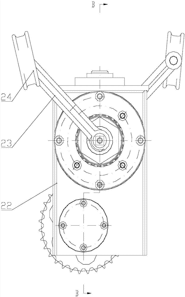
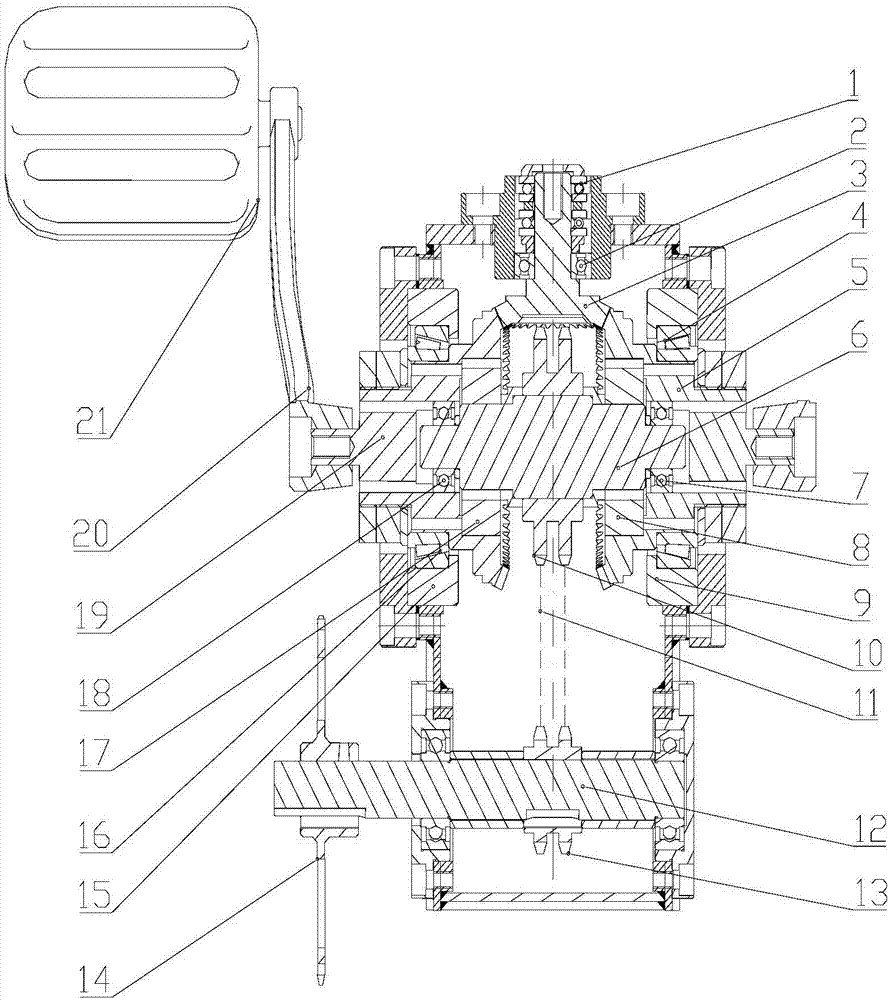
[0030] Such as Figures 1 to 2 shown. The invention discloses a bicycle crank up and down reciprocating swing driving device, which comprises: a one-way thrust ball bearing 1, a deep groove ball bearing 2, a front bevel gear 3, a right rolling bearing 4, a right bevel gear 5, a middle shaft 6, a right deep Groove ball bearing 7, right one-way clutch 8, right bearing seat 9, front double-row sprocket 10, chain 11, rear axle 12, rear double-row sprocket 13, left bearing seat 15, left rolling bearing 16, left one-way clutch 17. Left deep groove ball bearing 18, left bevel gear 19, left crank 20, left pedal 21, box 22, right crank 23, right pedal 24;

[0031] The front bevel gear 3 is placed on the deep groove ball bearing 2 and the one-way thrust ball bearing 1, and is fixed with the box body 22 through the bearing seat;

[0032] The front double-row sprocket 10 is fixed on the central shaft 6, and the left one-way clutch 17 and the right one-way clutch 8 are connected with the...


PUM


Abstract

The invention discloses a device and method for driving a crank of a bicycle to perform vertical reciprocating swing. The device comprises a single-directional thrust ball bearing, deep groove ball bearings, a front bevel gear, left and right rolling bearings, left and right bevel gears, a middle shaft and other parts. Two rows of front chain wheels are fixed to the middle shaft, and a left one-way clutch and a right one-way clutch are connected with two ends of the middle shaft through keys. One end of the left bevel gear and one end of the right bevel gear are connected with the left one-way clutch and the right one-way clutch respectively through keys, are put on the left rolling bearing and the right rolling bearing respectively and then are fixed to a box body through a left bearing seat and a right bearing seat. The left bevel gear and the right bevel gear are respectively meshed with the front bevel gear. Two ends of the middle shaft are put in shaft holes of the left bevel gear and the right bevel gear through the deep groove ball bearings. When the bicycle is ridden, a normal walking posture of a human body is simulated and conforms to the physiological habits of the human body, and the 'dead point' phenomenon occurred in the riding process of a traditional bicycle is avoided.

Description

technical field [0001] The invention relates to a driving mechanism for riding a bicycle, in particular to a crank up and down reciprocating swing driving device and method for a bicycle. Background technique [0002] Bicycle is one of the means of transportation that people like, and it is also a way for people to have fun and exercise. In recent years, people's growing demand for a leisurely and healthy life experience has prompted the design of bicycles to fully consider the factors of the human body, and at the same time fully consider the characteristics of use by different groups of people and occasions, so that the design of bicycles is moving towards "occupation of less space". , flexible and convenient, comfortable and durable" and other characteristics continue to develop. [0003] The drive mechanism that bicycle adopts now is to connect two pedals and crank by axis. In the process of applying force, the soles of the feet drive the crank to rotate through the fo...

Claims


Application Information

Patent Timeline
IPC IPC(8): B62M1/24
CPCB62M1/24
Inventor 吴上生王红飞喻钟鸣
Owner SOUTH CHINA UNIV OF TECH
Learn More