Communication method and device in a large-scale mimo
A signal and signal identification technology, applied in the field of mobile communication, can solve problems such as interference, low transmission power of a single antenna, UE pollution, etc.
- Summary
- Abstract
- Description
- Claims
- Application Information
AI Technical Summary
Problems solved by technology
Method used
Image


Examples
Embodiment 1
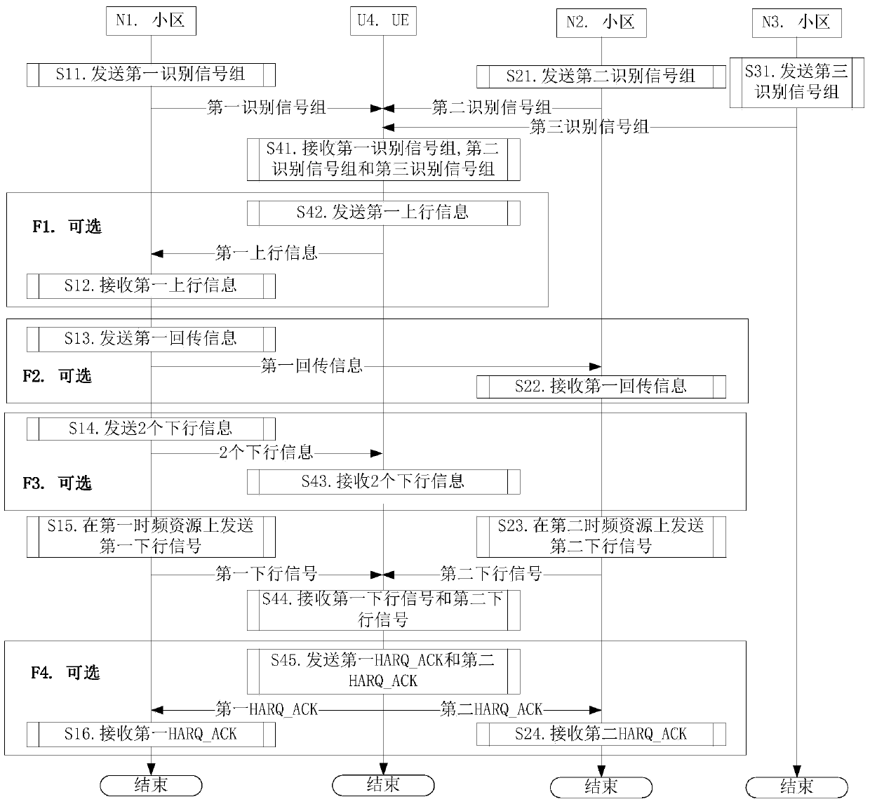
[0153] Embodiment 1 illustrates the flow chart of UE maintaining connection with multiple cells, as shown in the attached figure 1 shown. attached figure 1 Among them, cell N1 is the primary serving cell of UE U4. N1 cell, N2 cell and N3 cell are respectively maintained by 3 base stations. attached figure 1 , the steps in box F1, box F2, box F3 and box F4 are optional steps respectively.
[0154] For N1, send the first identification signal group in step S11, receive the first uplink information in step S12, send the first return information in step S13, send two downlink information in step S14, and send the first uplink information in step S15. The first downlink signal is sent on the first time-frequency resource, and the first HARQ_ACK is received in step S16.
[0155] For N2, send the second identification signal group in step S21, receive the first return information in step S22, send the second downlink signal on the second time-frequency resource in step S23, and ...
Embodiment 2
[0166] Embodiment 2 illustrates a schematic diagram of time resources and frequency resources occupied by an identification signal, as shown in the attached figure 2 shown. attached figure 2 In , the square marked with a slash is the time-frequency block occupied by one transmission of an identification signal.
[0167] In Embodiment 2, the identification signal is sent periodically, and the sending period is T (in milliseconds), where T is a positive rational number.
[0168] As a sub-embodiment 1 of Embodiment 2, each identification signal of the identification signal group in the present invention appears only once within a sending cycle.
[0169] As a sub-embodiment 2 of Embodiment 2, one transmission of the identification signal occupies W time windows in the time domain, where W is a positive integer greater than 1.
[0170] As a sub-embodiment 3 of Embodiment 2, one transmission of the identification signal occupies the attached figure 2 Part of the resource unit...
Embodiment 3
[0174] Embodiment 3 illustrates a schematic diagram of time resources and frequency resources occupied by two identification signals, as shown in the attached image 3 shown. attached image 3 In the figure, the square marked by the slash is the time-frequency block occupied by one transmission of an identification signal, that is, the identification signal I, and the square marked by the backslash is the time-frequency block occupied by one transmission of an identification signal, that is, the identification signal II .
[0175] In Embodiment 3, the identification signal I and the identification signal II respectively occupy different (one or more) time windows.
[0176] As a sub-embodiment 1 of Embodiment 3, an identification signal is sent once (ie aperiodically).
PUM
 Abstract
Description
Claims
Application Information
 - R&D
- Intellectual Property
- Life Sciences
- Materials
- Tech Scout
- Unparalleled Data Quality
- Higher Quality Content
- 60% Fewer Hallucinations
Browse by: Latest US Patents, China's latest patents, Technical Efficacy Thesaurus, Application Domain, Technology Topic, Popular Technical Reports.
© 2025 PatSnap. All rights reserved.Legal|Privacy policy|Modern Slavery Act Transparency Statement|Sitemap|About US| Contact US: help@patsnap.com