
Free space optical communication device monitoring system and monitoring method based on wireless network

A space optical communication, free space technology, applied in transmission systems, electrical components, etc., can solve the problems of low automation and strong manual dependence, and achieve the effect of overcoming low alignment accuracy, convenient data transmission, and low cost

Inactive Publication Date: 2017-06-13
HUAZHONG UNIV OF SCI & TECH
View PDF4 Cites 1 Cited by
  • Summary
  • Abstract
  • Description
  • Claims
  • Application Information

AI Technical Summary

Problems solved by technology

[0006] In view of the above problems, the present invention proposes a wireless network-based monitoring system and method for free-space optical communication equipment, which realizes remote state control and adjustment of free-space optical communication equipment, and achieves the purpose of centralized control of multiple devices, solving the problem of prior art Existing problems such as low automation and strong manual dependence

Method used


Image

  • Free space optical communication device monitoring system and monitoring method based on wireless network
  • Free space optical communication device monitoring system and monitoring method based on wireless network
  • Free space optical communication device monitoring system and monitoring method based on wireless network

Examples


Embodiment Construction

[0027] In order to make the object, technical solution and advantages of the present invention clearer, the present invention will be further described in detail below in conjunction with the accompanying drawings and embodiments. It should be understood that the specific embodiments described here are only used to explain the present invention, not to limit the present invention. In addition, the technical features involved in the various embodiments of the present invention described below can be combined with each other as long as they do not constitute a conflict with each other.

[0028] Preferred embodiments of the present invention will be described in detail below in conjunction with the accompanying drawings.

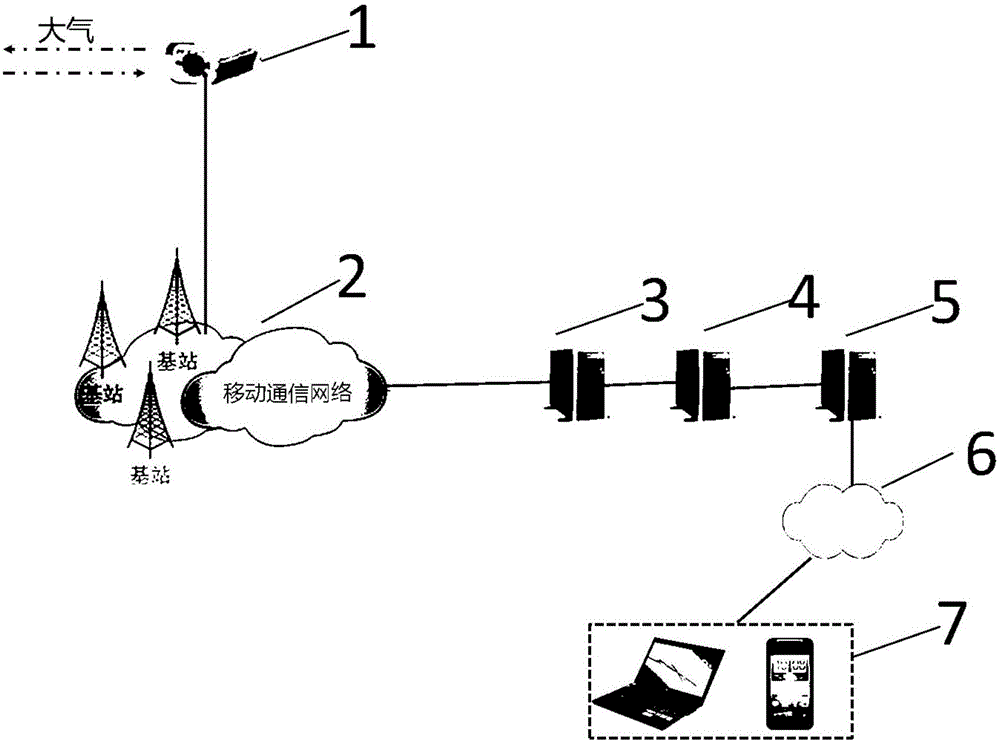
[0029] figure 1 It is a schematic structural diagram of a wireless network-based free-space optical communication equipment supervision system according to a preferred embodiment of the present invention.

[0030] As shown in the figure, the system includes: ...


PUM


Abstract

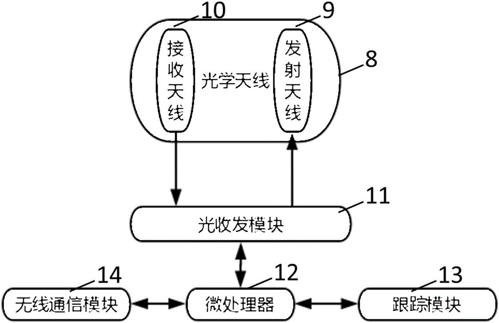
The invention discloses a free space optical communication device monitoring system and method based on a wireless network. The system comprises a free space optical communication device, a server and a monitoring platform. The free space optical communication device comprises an optical antenna, an optical transceiving module, a microprocessor, a tracking module and a wireless communication module. The method comprises the steps that the free space optical communication device sends data of the free space optical communication device to the server through a mobile communication network; the server stores and processes received data and then sends the data to the monitoring platform; the monitoring platform monitors the free space optical communication device according to the received data and sends a control instruction to the server; and the server sends the instruction to the free space optical communication device for adjustment. According to the system and the method, the filed data of the free space optical communication device can be directly obtained from the Internet, and the free space optical communication device is remotely monitored and managed without limitations of field wiring and the space position of the space wireless optical communication device.

Description

technical field [0001] The invention relates to a wireless network monitoring system and method, in particular to a wireless network-based free space optical communication equipment monitoring system and method. Background technique [0002] Optical signals can not only propagate in optical fibers, but also in air, and it is more convenient and faster. In the industry, the official name of wireless optical communication is FSO (Free Space Optical Communication). Compared with optical fiber communication, this communication method has a great cost advantage. [0003] Free space optical communication has broad application prospects in both military and civilian fields. The alignment of optical paths in free space optical communication is an important part of the system. How to align the optical paths of free-space optical communication devices is a problem that must be solved. [0004] The traditional optical path alignment is adjusted manually or controlled by an external ...

Claims


Application Information

Patent Timeline
IPC IPC(8): H04L29/06H04L29/08
CPCH04L67/025H04L67/01
Inventor 赵茗费良俊杨振宇
Owner HUAZHONG UNIV OF SCI & TECH
Learn More