Antenna device

An antenna device and loop antenna technology, applied in the field of communication, can solve the problems of cumbersome process, occupation, increase stacking complexity, etc., and achieve the effect of low complexity

Inactive Publication Date: 2017-06-13
AAC TECH NANJING
View PDF4 Cites 12 Cited by
  • Summary
  • Abstract
  • Description
  • Claims
  • Application Information

AI Technical Summary

Problems solved by technology

However, the inventors of the present invention have found that, in the prior art, it is difficult to meet the requirements of CA or many states need to be switched to achieve the implementation in the prior art, and the process is extremely cumbersome. Occupies more area, increases the complexity of stacking, and introduces the problem of isolation between multiple antennas

Method used


Image

  • Antenna device
  • Antenna device
  • Antenna device

Examples


Embodiment Construction

[0018] In order to make the objectives, technical solutions, and advantages of the present invention clearer, the various embodiments of the present invention will be described in detail below with reference to the accompanying drawings. However, a person of ordinary skill in the art can understand that, in each embodiment of the present invention, many technical details are proposed for the reader to better understand the present invention. However, even without these technical details and various changes and modifications based on the following embodiments, the technical solution claimed by the present invention can be realized.

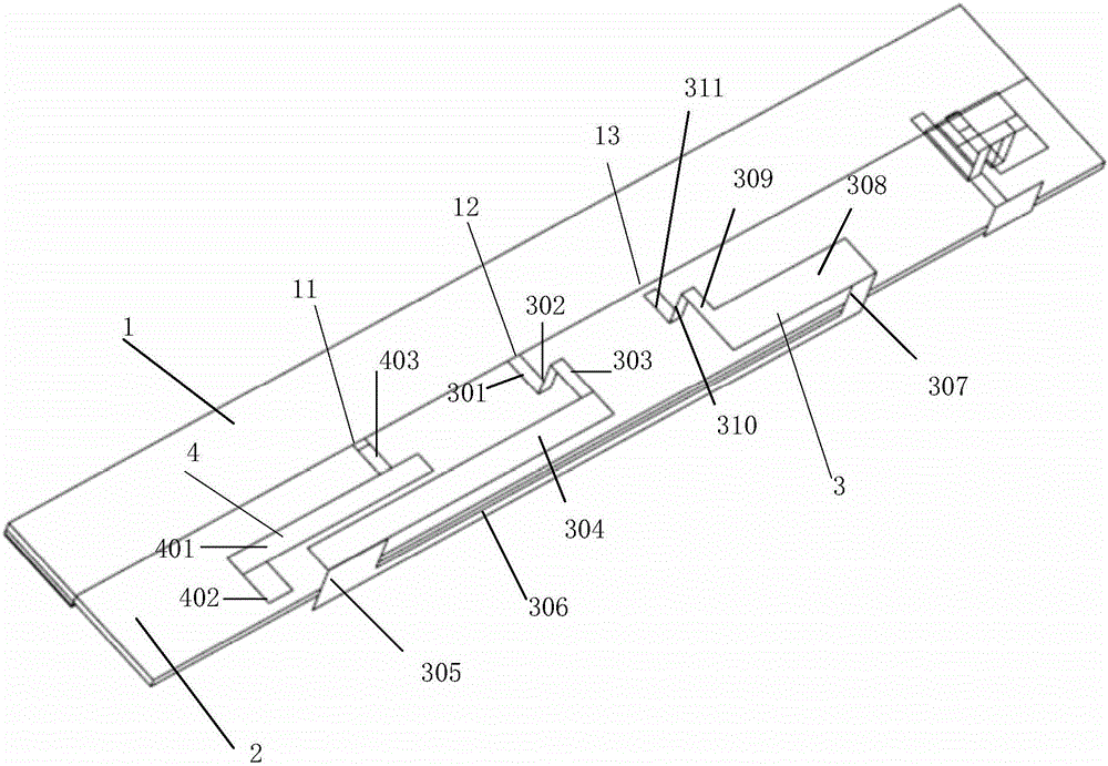
[0019] The first embodiment of the present invention relates to an antenna device. Such as figure 1 As shown, the antenna device includes a circuit board 1, a housing 2 accommodating the circuit board 1, and an antenna radiator disposed on the housing 2.

[0020] The circuit board 1 is provided with a feeding point 11, a grounding point 12 and a matchi...


PUM


Abstract

The invention relates to the field of communications, and discloses an antenna device. The antenna device comprises a circuit board provided with a feed point and a ground point and a shell containing the circuit board, an antenna radiator is arranged on the shell and comprises a loop antenna working in a multiband and a capacitive feed unit which is separated from the loop antenna in a spaced mode and works in a high-frequency band; one end of the loop antenna is electrically connected with a matching circuit arranged on the circuit board, and the other end of the loop antenna is connected with the ground point; the capacitive feed unit is connected with the feed point, the capacitive feed unit and the partial loop antenna are arranged in parallel to achieve capacitive feed; the matching circuit comprises an inductor and a radio frequency adjustable capacitor electrically connected with the inductor in parallel to achieve low-frequency tuning on the loop antenna so as to cover the whole low frequency. Compared with the prior art, communication full band covering can be achieved simply by switching three to four states.

Description

Technical field [0001] The present invention relates to the field of communication, in particular to an antenna device. Background technique [0002] With the rapid development of communication technology, LTE (Long Term Evolution) requires antennas to cover more and more frequency bands, while the low frequency (698-960MHz) and high frequency (LTE band11&21) frequency bands are more difficult to achieve. In the prior art, the above low frequency and high frequency are usually realized by adding an RF switch or tuner divided state, or realized by dividing frequency bands by multiple antennas. However, the inventor of the present invention found that, in the prior art, when the state is implemented, it is difficult to meet the CA requirements or needs to switch many states to achieve, and the process is extremely cumbersome; and when multiple antennas are implemented in frequency bands, the multiple antennas will not only Occupies more area, increases the complexity of stacking, ...

Claims


Application Information

Patent Timeline
IPC IPC(8): H01Q23/00H01Q7/00H01Q1/50H01Q5/20H01Q5/314
CPCH01Q1/50H01Q5/20H01Q5/314H01Q7/00H01Q23/00
Inventor 武景
Owner AAC TECH NANJING
Why Eureka
Try Eureka