
Spacecraft solar panel conformal antenna

A technology of solar panels and conformal antennas is applied in the field of antennas and spacecraft antennas to achieve strong reproducibility, broad application prospects and good scalability.

Active Publication Date: 2017-06-13
耿文东
View PDF2 Cites 18 Cited by
  • Summary
  • Abstract
  • Description
  • Claims
  • Application Information

AI Technical Summary

Problems solved by technology

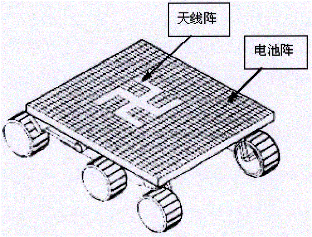
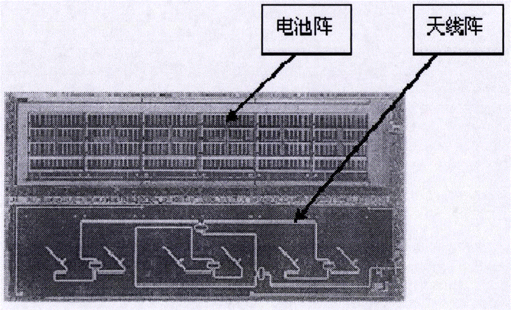
At present, there is no precedent for using the back of the solar panel substrate as a carrier to form a conformal antenna with the battery array

Method used


Image

  • Spacecraft solar panel conformal antenna
  • Spacecraft solar panel conformal antenna
  • Spacecraft solar panel conformal antenna

Examples


Embodiment Construction

[0049] Taking the dual-band array design of the S-band array element and the X-band array element as an example, the present invention will be further described.

[0050] Select the S and X frequency bands, the center frequencies are 3GHz and 10GHz respectively, and the corresponding wavelengths are 0.1m and 0.03m respectively. The antenna beam coverage form is omnidirectional coverage, multi-beam working mode. The size of the solar panel substrate is set to a total of 20m2 usable area for the two wings.

[0051] 1) Structural design of solar panel conformal antenna dual-frequency array

[0052] Since the frequency ratio of the X-band and the S-band is close to 3, smaller X-band units can be embedded in the gaps of the S-band unit array to meet the need for a shared array aperture. The array uses a series feed to reduce the difficulty of layout of the feed network, and uses a symmetrical design to reduce the influence of beam tilt with frequency.

[0053] The cross-section ...


PUM


Abstract

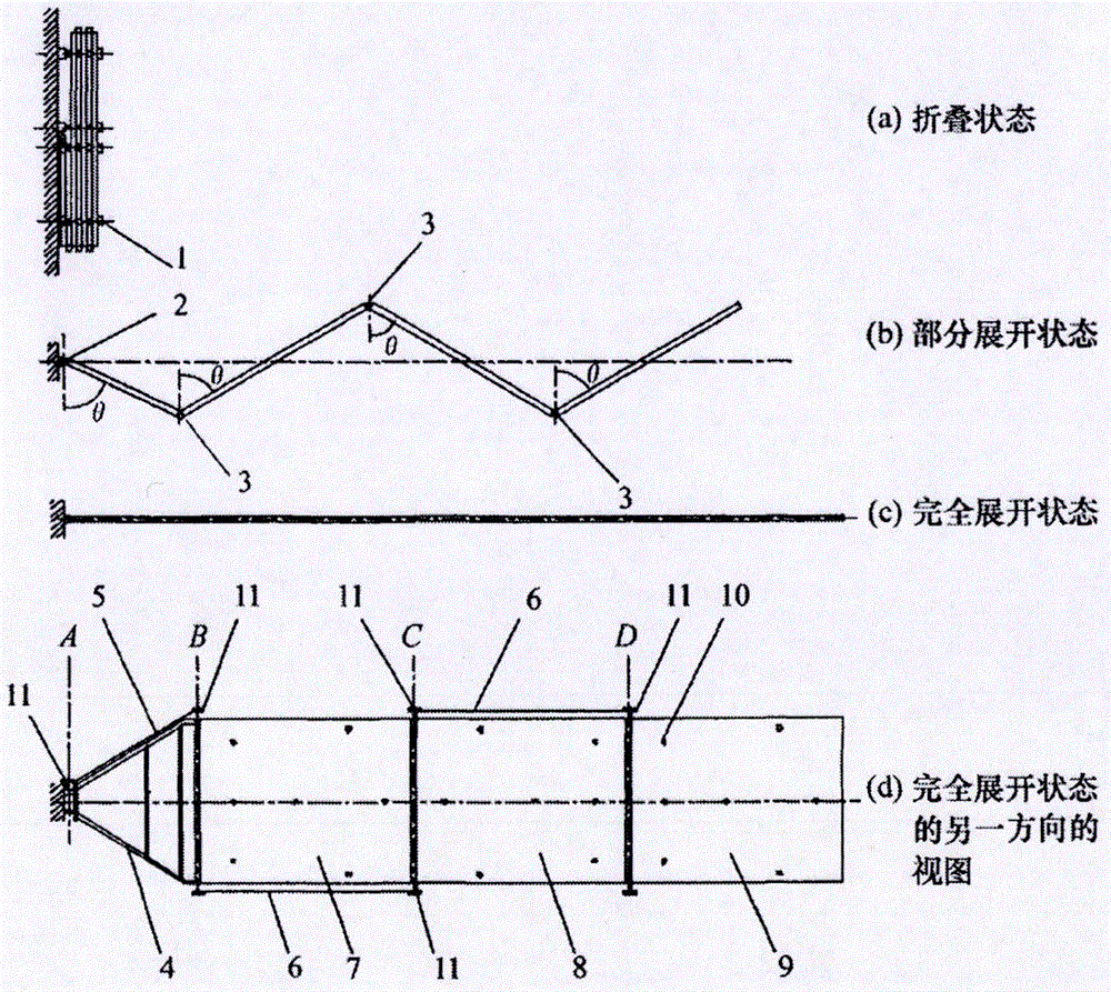
On the basis of defining the concept of a spacecraft solar panel conformal antenna, the invention discloses S1, a spacecraft solar panel conformal antenna structure; S2, a spacecraft solar panel conformal antenna array structure; S3, a spacecraft solar panel conformal antenna array feeding mode; S4, a spacecraft solar panel conformal antenna beam control network; S5, a spacecraft solar panel conformal antenna microwave signal transmission line; S6, a connecting method of the spacecraft solar panel conformal antenna and a spacecraft. The spacecraft solar panel conformal antenna has the advantages of reducing the spacecraft launching cost, prolonging the in-orbit service life of the spacecraft, reducing the fairing requirement, facilitating appearance attractiveness of the spacecraft, improving spacecraft maneuverability and safety, and being high in replicability and good in expandability. Multiple solar panel conformal antennas with different orbit heights and types can be applied through networking, and cover with a bigger bandwidth range and a wider spatial range can be achieved through mission planning. Besides, the conformal antenna thought can be expanded to the field of interstellar probe antennas. The spacecraft solar panel conformal antenna has a wide application prospect.

Description

technical field [0001] The invention belongs to the field of antennas, in particular to the field of spacecraft antennas. Background technique [0002] Antennas are an integral part of any spacecraft, and spacecraft for different purposes require different antennas, which are used for information transmission between uplinks, downlinks, and spacecraft. As an electromagnetic energy converter, the existing antennas used by spacecraft can be divided into wire antennas, horn antennas, reflector antennas and array antennas according to the antenna form. The spacecraft antenna is installed on its outer surface. In order to meet the needs of different purposes, multiple antennas of different types are usually installed. In order to meet the needs of high gain, the antenna area is usually increased, and it becomes the most visible part of the spacecraft. Therefore, there is a caliber Large, deep profile, high protrusion and large number, and more complex deployment control system, ...

Claims


Application Information

Patent Timeline
Patent Type & Authority Applications(China)
IPC IPC(8): H01Q1/38H01Q1/12H01Q1/50H01Q1/44
CPCH01Q1/12H01Q1/38H01Q1/44H01Q1/50
Inventor 耿歌张强赵媛媛耿文东杨丽
Owner 耿文东
Learn More