


Quick Research
Generate reliable direction feasibility study reports for your R&D in just a few steps.

Technical Q&A
Discover and master advanced knowledge NOW. Basics, ideas, possibilities, all at once.

Find Solutions
As an expert in R&D theories, this can generate solutions to your technical problems instantly.

Evaluate Feasibility
Analyze your overall solution with one click, know your potential R&D risks in advance.

Monitor Landscape
Get weekly tech updates, stay abreast of the latest tech innovations and key insights.
Laser radar device and detection method
A technology of laser radar and laser, which is applied in measuring devices, radio wave measuring systems, electromagnetic wave re-radiation, etc., can solve problems such as signal attenuation, achieve the effect of avoiding signal attenuation and providing detection performance
- Summary
- Abstract
- Description
- Claims
- Application Information
AI Technical Summary
Problems solved by technology
Method used
Image

Examples
Embodiment approach 1
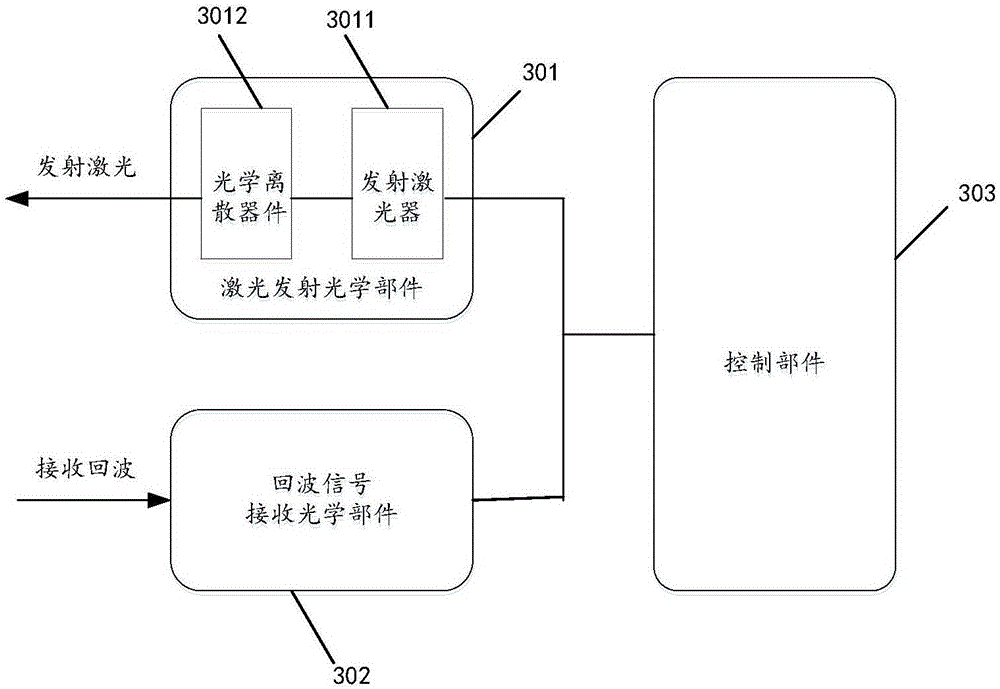
[0034] image 3 It is a feasible embodiment 1 proposed by the present invention. The laser radar device includes: a laser emitting optical component 301 for emitting spatially discrete laser light; an echo signal receiving optical component 302 for receiving reflected echo signals; a control Component 303, configured to perform signal processing on the received echo signal. It should be noted that the laser emitting optical component 301 in this solution is different from the existing flash laser radar. It not only includes the emitting laser 3011 for emitting laser light, but also includes an optical discrete device 3012, which is used to convert the laser light generated by the emitting laser The space is discretized to form a space discrete laser.
[0035] Figure 4 It is a flow chart of the method for detecting space targets by the laser radar device of the present invention. The emitting laser 3011 transmits the generated laser to the optical discrete device 3012 (step...
PUM
 Abstract
Description
Claims
Application Information
 - R&D Engineer
- R&D Manager
- IP Professional
- Industry Leading Data Capabilities
- Powerful AI technology
- Patent DNA Extraction
Browse by: Latest US Patents, China's latest patents, Technical Efficacy Thesaurus, Application Domain, Technology Topic, Popular Technical Reports.
© 2024 PatSnap. All rights reserved.Legal|Privacy policy|Modern Slavery Act Transparency Statement|Sitemap|About US| Contact US: help@patsnap.com