Engine power assembly mass and center of mass testing method
A technology of powertrain and testing method, which is applied in the testing of machines/structural components, static/dynamic balance testing, measuring devices, etc., and can solve the problems of low testing accuracy, time-consuming and labor-intensive testing, and poor testing accuracy.
Inactive Publication Date: 2017-06-13
GUANGXI UNIV
View PDF4 Cites 4 Cited by
- Summary
- Abstract
- Description
- Claims
- Application Information
AI Technical Summary
Problems solved by technology
The three-line pendulum method needs to repeatedly adjust the attitude of the object under test (more than 6 to 7 times) to test the center of mass of the powertrain. The test process is time-consuming and laborious.
The basic principles of the bracket method and the triangular base moment balance method are to solve the mass center of the powertrain und
Method used
View moreImage
Smart ImageViewing Examples
Examples
 PUM
 Abstract
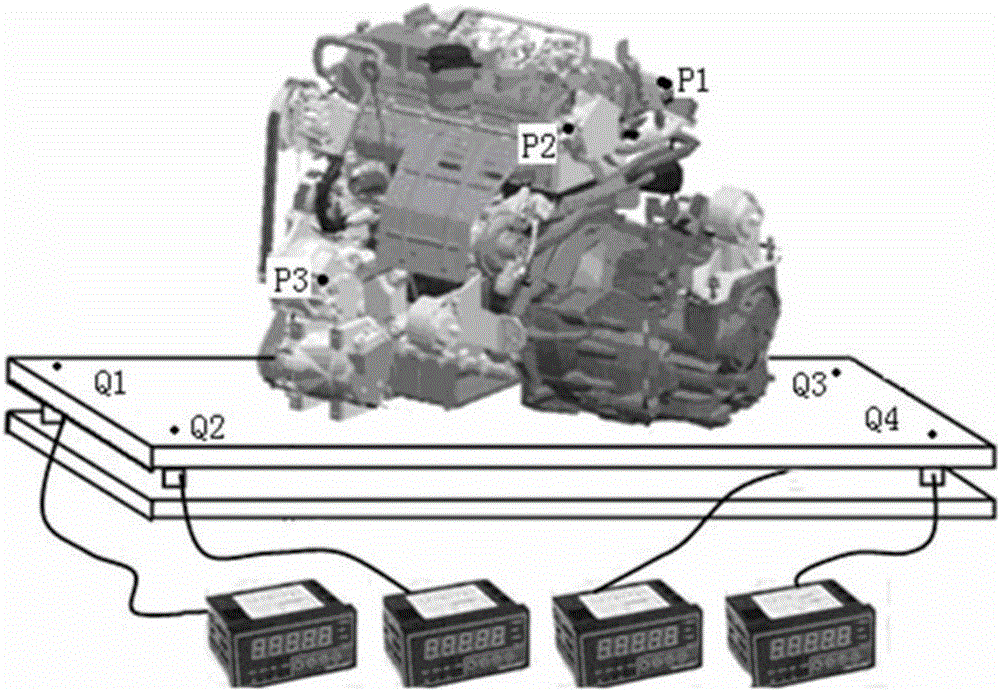
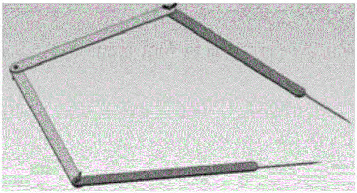
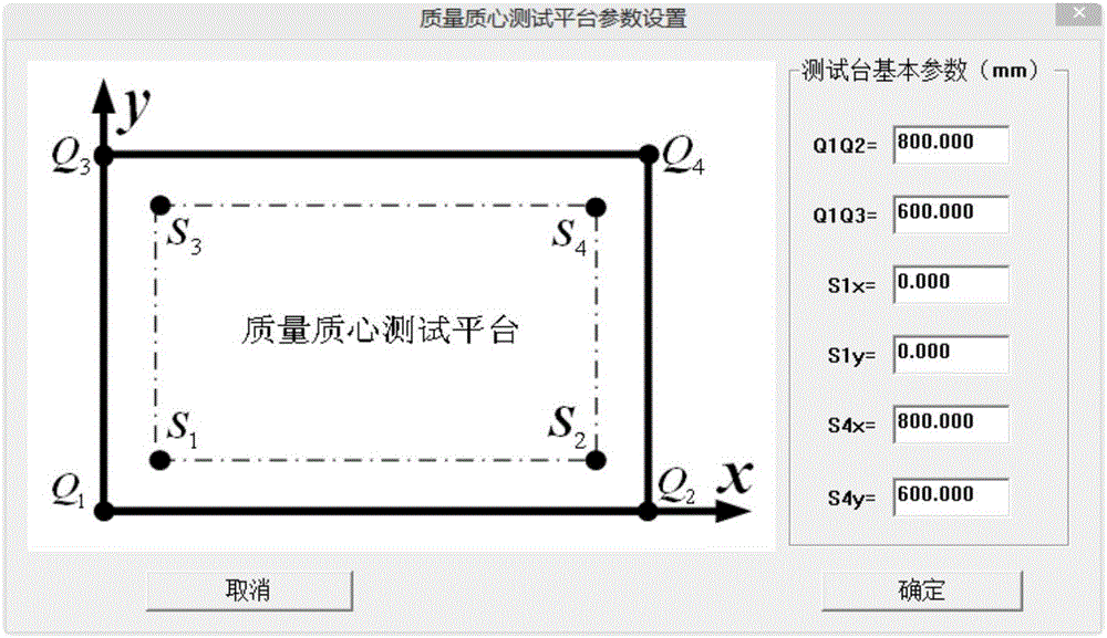
The invention discloses an engine power assembly mass and center of mass testing method. The method comprises the steps of putting an engine power assembly on a test platform supported by a pressure sensor; then measuring a distance from a power assembly preset reference point to a test platform support point, reading a reading value displayed on the pressure sensor, changing a putting posture of the power assembly, repeating the processes above for 2-3 times, utilizing positions of four corner points of the test platform, coordinates of three reference points on the power assembly in a power assembly coordinate system and the above measured distance and displayed reading value to calculate and obtain coordinate data of an engine power assembly mass and center of mass in the power assembly coordinate system. Compared with the prior art, the engine power assembly mass and center of mass testing method has the advantages that the size of the power assembly to be measured is not limited, and the putting position and posture angle do not need to be mutually perpendicular; the number of times of putting the power assembly to be measured is few, and measuring is simple and convenient; the test theory and algorithm are novel, and corresponding calculation software is created originally; evaluation can be conducted on the test operation process, and thus it is ensured that the test result has high precision.
Description
technical field [0001] The invention belongs to the technical field of testing the center of mass of a rigid body, in particular to a method for testing the center of mass of an engine power assembly. [0002] technical background [0003] Automobile powertrain is an assembly composed of engine and transmission. Accurate data of the mass of the powertrain of the automobile engine and the position of the center of mass in the powertrain are important basic data indispensable for the design of automobile balance and vibration reduction. However, because the internal structure of the powertrain is very complex, it is difficult to establish an accurate digital model for structural numerical analysis, so the center of mass of the powertrain is difficult to obtain by structural numerical analysis and calculation, and generally must be obtained through actual testing. At present, there are mainly theodolite test method, grating displacement test method, motion equation solution met...
Claims
Login to View More Application Information
Patent Timeline
 IPC IPC(8): G01M1/12
CPCG01M1/122
Inventor 陈树勋韦齐峰陈瑞兵
Owner GUANGXI UNIV
Features
- R&D
- Intellectual Property
- Life Sciences
- Materials
- Tech Scout
- Unparalleled Data Quality
- Higher Quality Content
- 60% Fewer Hallucinations
Learn More Browse by: Latest US Patents, China's latest patents, Technical Efficacy Thesaurus, Application Domain, Technology Topic, Popular Technical Reports.
© 2025 PatSnap. All rights reserved.Legal|Privacy policy|Modern Slavery Act Transparency Statement|Sitemap|About US| Contact US: help@patsnap.com


