Gear box of fan

A technology of fan gear box and gear box, applied in the direction of belt/chain/gear, non-variable-capacity pump, transmission parts, etc.

Active Publication Date: 2017-06-13
李力光
View PDF6 Cites 1 Cited by
  • Summary
  • Abstract
  • Description
  • Claims
  • Application Information

AI Technical Summary

Problems solved by technology

[0003] In order to solve the above problems, the object of the present invention is to provide a fan gearbox, the puller shaft and the worm gear are connected together, after the puller shaft is pulled out, the worm wheel can be separated from the motor shaft, but the puller shaft, the worm wheel and the worm shaft are mutually There will be no separation between them, so there will be no deviation of the connection between the worm wheel and the worm gear shaft when pulling out and pressing the pumping shaft, so that the pumping shaft cannot be pressed down, so it can ensure that the shaking head function of the fan will not appear abnormal

Method used


Image

  • Gear box of fan
  • Gear box of fan
  • Gear box of fan

Examples


Embodiment Construction

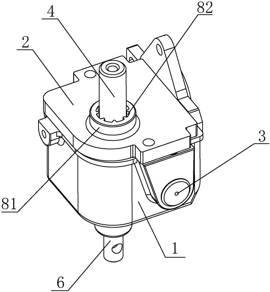
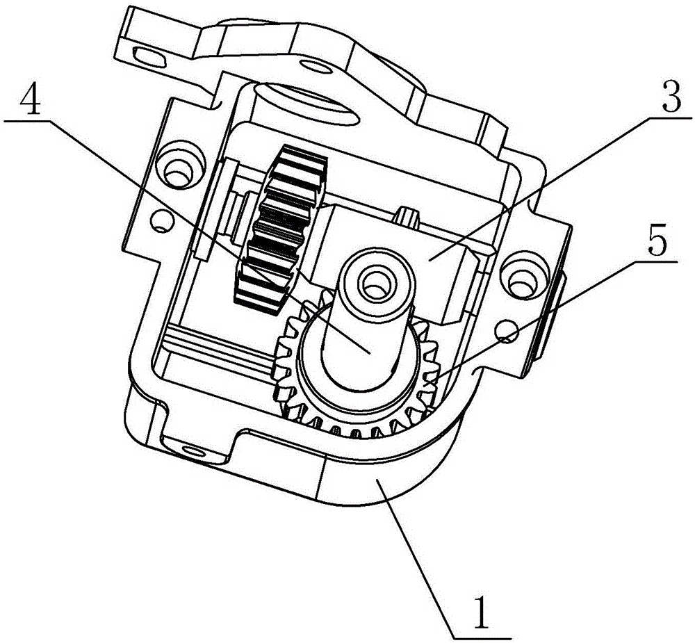
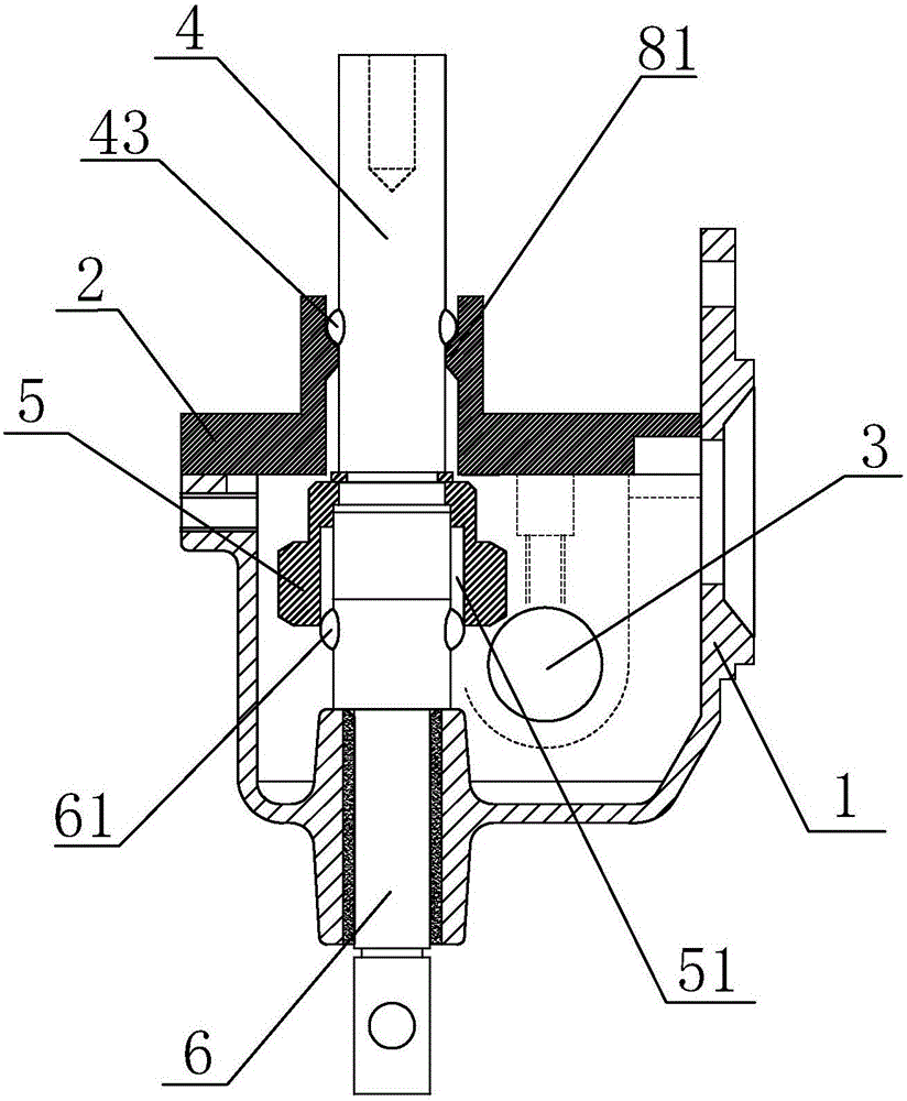
[0022] refer to Figure 1-Figure 8 , a fan gearbox, including a gearbox body 1 and a case cover 2, the gearbox body 1 is provided with a motor shaft 3 inserted into the gearbox body 1 by a fan motor, and a handle for shaking the fan Shaft 4, worm gear 5 for transmission and worm gear shaft 6 for driving the fan to shake the head. The puller shaft 4 extends to the outside of the gearbox body 1 through the puller through hole arranged in the box cover 2. The worm gear shaft 6 extends to the outside of the gearbox body 1 through the through hole of the worm shaft in the gearbox body 1, the worm wheel 5 and the motor shaft 3 are meshed together, the inside of the worm wheel 5 is provided with a groove 51, and the worm wheel shaft 6 is provided There is a connecting protrusion 61 that cooperates with the groove 51. The worm wheel 5 is arranged on the bottom of the handle shaft 4, and the connecting protrusion 61 is arranged in the groove 51. When the handle shaft 4 is pulled out, t...


PUM


Abstract

The invention discloses a gear box of a fan. The gear box comprises a gear box body and a box cover, wherein a motor shaft, a hand-pulling shaft, a worm wheel and a worm-wheel shaft are arranged in the gear box body; the hand-pulling shaft stretches to the exterior of the gear box body through a hand-pulling through hole; the worm-wheel shaft stretches to the exterior of the gear box body through a worm-wheel shaft through hole; the worm wheel is mutually meshed with the motor shaft together; a groove is arranged in the interior of the worm wheel; the worm-wheel shaft is provided with a connecting bulge; the worm wheel is arranged at the bottom of the hand-pulling shaft; the connecting bulge is arranged in the groove; when the hand-pulling shaft is pulled up, the worm wheel upwards moves along the connecting bulge to leave the motor shaft but not to disengage the connecting bulge. When the handle shaft is pulled up, the worm wheel can leave the motor shaft, but the hand-pulling shaft, the worm wheel and the worm-wheel shaft cannot be separated mutually; therefore, the condition that the groove and the connecting bulge generate deflection to cause that the hand-pulling shaft cannot be pressed down cannot occur when the handle shaft is pulled and pressed; therefore, an exception can be guaranteed not to occur to the head shaking function of the fan.

Description

technical field [0001] The invention relates to the field of oscillating fans, in particular to a fan gear box. Background technique [0002] The current oscillating fans all have a gear box, and when the puller in the gear box is pulled up or pressed down, a corresponding effect on the oscillating head of the fan can be realized. In the structure of the existing fan gear box, such as the gear box structure of the horn fan, the pumping shaft, the worm wheel and the worm shaft are independently separated from each other, and the pumping shaft is connected with the worm wheel and the worm shaft through a buckle. When the hand shaft is connected with the worm wheel and the worm shaft, the motor shaft drives the worm wheel to rotate, and the worm wheel drives the hand shaft to rotate through the buckle, so the worm wheel shaft rotates under the drive of the hand shaft, so that the fan shakes its head; When the hand shaft is used, the hand shaft leaves the worm wheel, and the wo...

Claims


Application Information

Patent Timeline
Patent Type & Authority Applications(China)
IPC IPC(8): F16H57/039F04D25/10
CPCF04D25/105F16H57/039Y02E10/72
Inventor 李力光
Owner 李力光
Why Eureka
Try Eureka