


Quick Research
Generate reliable direction feasibility study reports for your R&D in just a few steps.

Technical Q&A
Discover and master advanced knowledge NOW. Basics, ideas, possibilities, all at once.

Find Solutions
As an expert in R&D theories, this can generate solutions to your technical problems instantly.

Evaluate Feasibility
Analyze your overall solution with one click, know your potential R&D risks in advance.

Monitor Landscape
Get weekly tech updates, stay abreast of the latest tech innovations and key insights.
Worm reducer with intelligent monitoring system
An intelligent monitoring system, the technology of worm gear reducer, applied in the direction of belt/chain/gear, mechanical equipment, gear transmission, etc., can solve the problems of oil-free lubrication and dry friction, the reducer does not know when to change the oil, etc., to avoid the use of Life, avoid rapid temperature rise or oil leakage and deterioration failure, the effect of long service life
- Summary
- Abstract
- Description
- Claims
- Application Information
AI Technical Summary
Problems solved by technology
Method used
Image

Examples
Embodiment 1
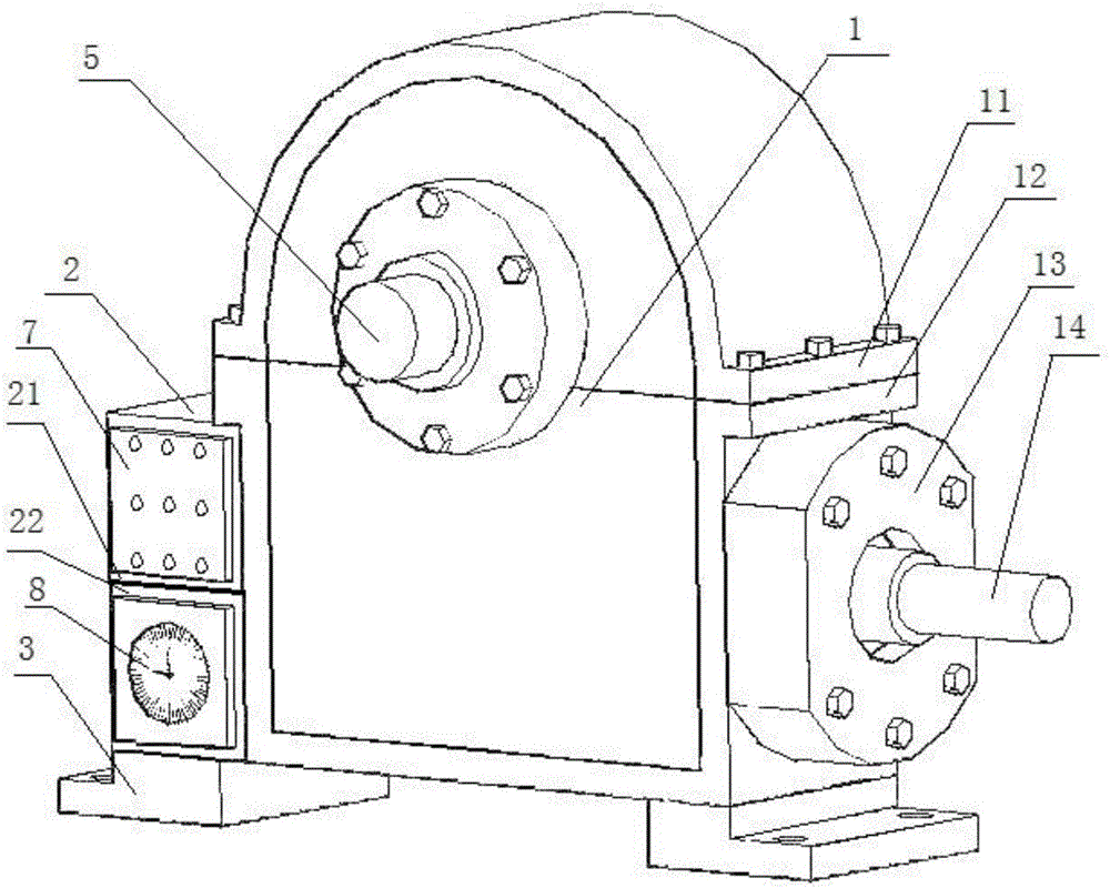
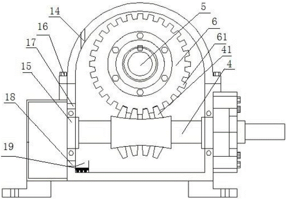
[0019] Such as Figure 1-Figure 2 As shown, a worm gear reducer with an intelligent monitoring system includes an oil tank 1, a worm gear 6 and a worm 4 that mesh with each other, and a fixed orifice 3 that is co-cast with the oil tank 1 is provided under the oil tank 1. The oil tank 1 The bearing 15 for installing the worm gear 6 and the worm screw 4 is installed inside, and the oil tank 1 is filled with lubricating oil at least not past the meshing position of the worm gear 6 and the worm screw 4, and the worm gear 6 is connected with an output shaft 5 extending to the outside of the oil tank 1. The top of 1 is provided with an alarm device hole 14 communicating with the inner cavity of the fuel tank 1. The diameter of the alarm device hole 14 is 8-10 mm. A imaging glass tube is inserted into the alarm device hole 14. The imaging glass The lower end of the tube extends below the position where the worm wheel 6 and the worm screw 4 are engaged with each other. A photoelectric...
Embodiment 2
[0022] Further optimized on the basis of a worm gear reducer with an intelligent monitoring system described in Embodiment 1, one end of the worm 4 extends to the outside of the fuel tank 1, and the connection between the output shaft 5 and the worm 4 and the fuel tank 1 is provided with A sealing cover 13 to prevent lubricating oil from leaking. The side of the oil tank 1 is provided with an auxiliary oil tank 2 for self-circulation cooling and storage of the lubricating oil. The upper oil hole 17 and the lower oil hole 18 of circulation.
[0023] The reducer provided in this embodiment is changed from a single fuel tank to a double fuel tank square structure with fuel tank 1 and auxiliary fuel tank 2. The fuel tank 1 is used to install the worm gear 6 and the worm 4. The worm gear 6 and the worm 4 are the heart of the reducer, and the auxiliary fuel tank 2 is used. The cold and hot self-circulation of lubricating oil is carried out in the auxiliary oil tank 1, and the high-s...
Embodiment 3
[0026] Such as figure 2 As shown, further optimization is carried out on the basis of the new high-end reducer with lubricating oil cooling and heating self-circulation described in Example 1, so that it has the function of automatically absorbing lubricating oil residues, ensuring that the lubricating oil remains clear for a long time, and the lower oil hole 18 The bottom of the oil tank 1 below and the bottom of the fuel tank 1 on the opposite side of the lower oil hole 18 are provided with a dregs storage tank 19, and the size of the dregs storage tank 19 is 30*15*15 mm. The magnet is fixed with the dregs storage tank 19 through the insulating plate or insulating glue bonded at its bottom, and the notch of the dregs storage tank 19 is provided with a 35*10*1 mm stopper to prevent the dregs from being stored in the dregs storage tank 19. Along with the cold and hot self-circulation movement of the oil, it is re-entangled in the box. The purpose of the present embodiment is ...
PUM
 Abstract
Description
Claims
Application Information
 - R&D Engineer
- R&D Manager
- IP Professional
- Industry Leading Data Capabilities
- Powerful AI technology
- Patent DNA Extraction
Browse by: Latest US Patents, China's latest patents, Technical Efficacy Thesaurus, Application Domain, Technology Topic, Popular Technical Reports.
© 2024 PatSnap. All rights reserved.Legal|Privacy policy|Modern Slavery Act Transparency Statement|Sitemap|About US| Contact US: help@patsnap.com