
Magnetic attraction type plate structure

A magnetic suction type and plate technology, which is applied in the direction of building structure, coating, construction, etc., can solve the problems of inability to achieve convenient operation, narrow splicing gaps, etc.

Inactive Publication Date: 2017-06-13
QING YUAN KUAI DI NEW BUILDING MATERIALS CO LTD
View PDF5 Cites 8 Cited by
  • Summary
  • Abstract
  • Description
  • Claims
  • Application Information

AI Technical Summary

Problems solved by technology

[0004] The decorative panels in the prior art are generally unable to achieve the effects of convenient operation, easy disassembly and assembly, and narrow splicing gaps

Method used


Image

  • Magnetic attraction type plate structure
  • Magnetic attraction type plate structure
  • Magnetic attraction type plate structure

Examples


Embodiment 1

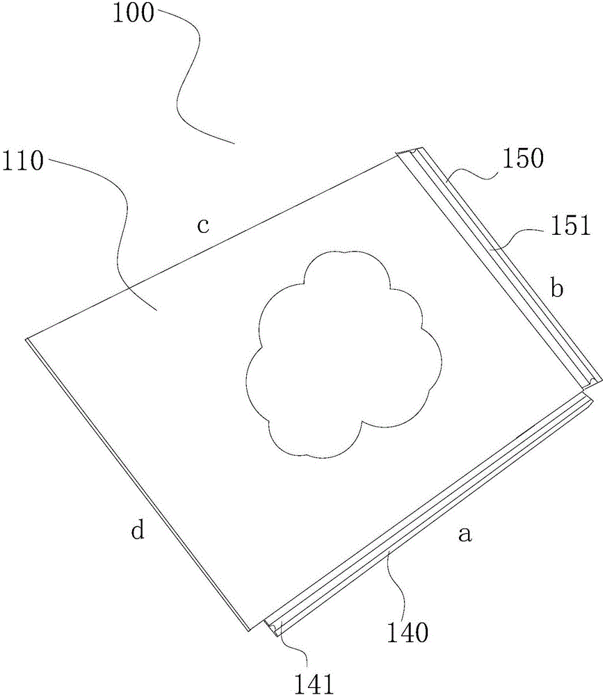
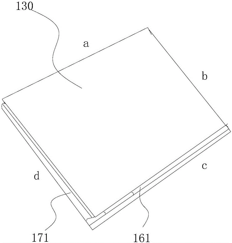
[0051] A magnetic plate structure, comprising: a magnetic coating arranged on a decorative surface to be installed and a plate 100 for magnetically attracting the magnetic coating, such as figure 1 , figure 2 shown.

[0052] Among them, the magnetic coating is applied to the decorative surface to be installed. The decorative surface to be installed can be the ground, or a wall or other building surfaces. By disposing a magnetic coating on the decorative surface to be installed, the plate 100 is fixedly installed on the decorative surface through the magnetic coating.

[0053] Specifically, the plate 100 is provided with a magnetic glue layer 110, a plastic shaped layer and a surface texture layer 130, the magnetic glue layer 110, the plastic shaped layer and the surface texture layer are sequentially stacked and fixedly connected, and the magnetic glue layer 110 is attracted to the magnetic coating. The magnetic adhesive layer 110 may be an adhesive layer containing iron p...

Embodiment 2

[0066] A magnetic plate structure, other features are the same as those of Embodiment 1, and also has the following technical features.

[0067] The preparation process of the magnetic coating includes the steps of pretreatment and coating treatment on the decorative surface;

[0068] The pretreatment is to coat the decorative film with an interface agent to form an interface agent layer, and seal the pores on the decoration surface through the interface agent layer, wherein the interface agent is a nanoscale water-based acrylic emulsion;

[0069] The coating treatment is to coat the magnetic coating on the surface of the interface layer to form the magnetic coating.

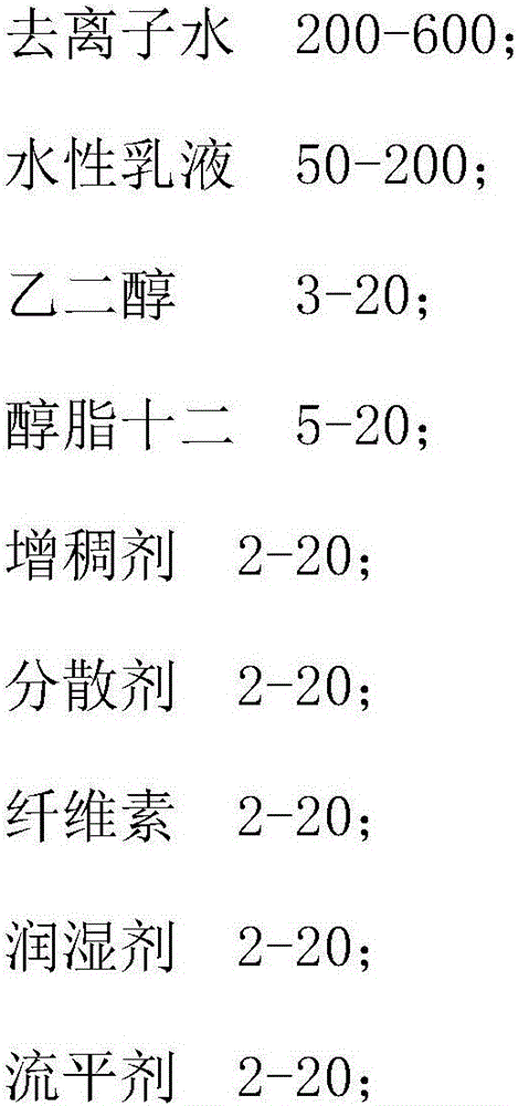
[0070] Specifically, the magnetic plate structure, in parts by weight, each part of the magnetic coating includes:

[0071]

[0072]

[0073] Among them, the water-based emulsion is acrylic acid, the preservative is a polyisothiazolone water-based mixture, the thickener is a water-based thickener, the cel...

Embodiment 3

[0077] A magnetic plate structure, the other features are the same as in Example 2, and also has the following technical features: the water-based emulsion is polyurethane. The basaltic magnetic coating of this formula has the characteristics of strong adsorption and good conductivity.


PUM


Abstract

The invention relates to a magnetic attraction type plate structure, which comprises a magnetic coating layer arranged on a decorated surface for mounting and a plate for being magnetically attracted to the magnetic coating layer; the magnetic coating layer is coated on the decorated surface for mounting; the plate is provided with a magnetic rubber layer, a plastic shaping layer and a surface texture layer, the magnetic rubber layer, the plastic shaping layer and the surface texture layer are sequentially superposed and fixedly connected by a heat bonding method, and the magnetic rubber layer and the magnetic coating layer are attracted to each other. By arranging the magnetic coating layer on the decorated surface for mounting, the invention prevents defects caused by needing to stick a magnetic rubber roll on the floor in the prior art, such as great thickness and inconvenience in operation.

Description

technical field [0001] The invention relates to the technical field of decorative plates, in particular to a magnetic plate structure. Background technique [0002] With the development of society, decorative panels are indispensable in people's home decoration. In the prior art, ceramic tiles, wood floors, and plastic composite floors are the main decorative boards. The paving of tiles requires pre-coating cement on the bottom layer, and then laying tiles, which is a complicated process. Wooden floors and plastic composite floors often have environmental problems because they need to be coated with glue, and they are not easy to disassemble. [0003] Regardless of whether it is used as a floor or as a board for other purposes, in most cases it is hoped that the splicing gap should be as narrow as possible to achieve a good decorative effect. [0004] The decorative panels in the prior art are generally unable to achieve the effects of convenient operation, easy disassemb...

Claims


Application Information

Patent Timeline
Patent Type & Authority Applications(China)
IPC IPC(8): E04F13/077E04F13/076E04F13/30C09D133/00C09D175/04C09D7/12
CPCC09D7/61C09D7/63C09D133/00C09D175/04E04F13/0866E04F13/0883E04F13/0894C08L1/284C08K13/02C08K5/47C08K5/053C08K5/103C08K3/00
Inventor 张小民
Owner QING YUAN KUAI DI NEW BUILDING MATERIALS CO LTD
Learn More