Post-modern clothes peg
A clamp body and chuck technology, applied in the field of post-modern clothespins, can solve the problems of insufficient clamping force, complex structure, inconvenient manufacturing, etc., and achieve the effect of simple manufacturing process, simple structure and strong clamping force
- Summary
- Abstract
- Description
- Claims
- Application Information
AI Technical Summary
Problems solved by technology
Method used
Image
Examples
Embodiment 1
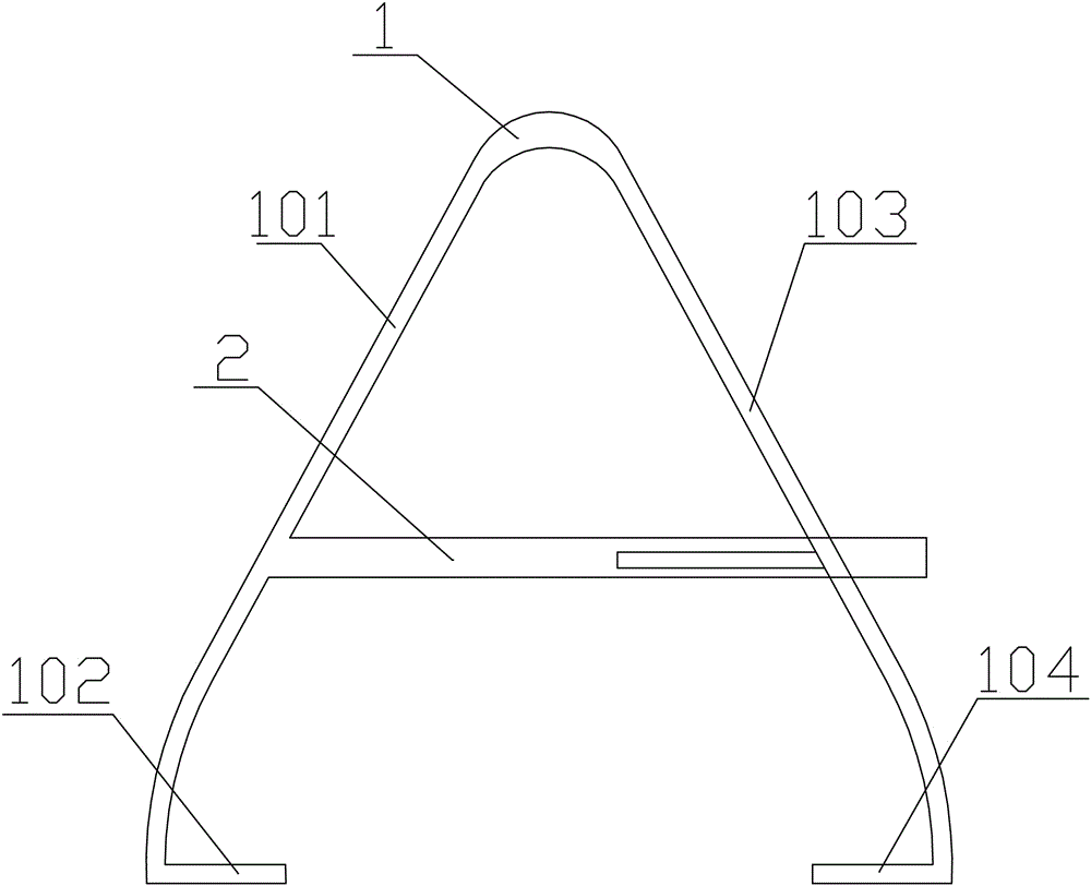
[0059] Such as Figure 1-2 , the locking mechanism adopts a toothed locking mechanism 2, the toothed locking mechanism 2 includes a toothed box 201, the toothed box 201 is fixed on the first clip body 101, and the inner wall of the toothed box 201 is processed with Alveolar 202, described alveolar 202 is arranged on the mating tooth 203 that is arranged on the second clip body 103 and cooperates to close up first clip body 101 and second clip body 103 and lock; The number of described alveolar 202 is more than one.
[0060] With the above-mentioned locking mechanism, during use, only the second clamp body 103 needs to be pressed into the inside of the gear box 201, and at this time, the cooperating gear teeth 203 will be engaged and locked with the tooth grooves 202, thereby ensuring the second A clip body 101 and a second clip body 103 are closed, and the clothes to be dried are clamped on the clothes rail through the first clip 102 and the second clip 104;
[0061] When it...
Embodiment 2
[0064] Such as Figure 3-4 , the locking mechanism adopts a single-tooth locking mechanism 3, and the single-tooth locking mechanism 3 includes a single-tooth box 301, and the single-tooth box 301 is fixed on the first clip body 101, and the single-tooth box A single tooth 303 is processed on the inner wall of the 301, and the single tooth 303 cooperates with the single mating tooth 302 on the second clamp body 103 to fix and lock the first clamp body 101 and the second clamp body 103 together; The ends of the first clip body 101 and the second clip body 103 are respectively provided with a first reed clip 105 and a second reed clip 106 .
[0065] Using the above-mentioned single-tooth locking mechanism 3 locking mechanism, during use, by kneading the first clamp body 101 and the second clamp body 103, the single mating gear tooth 302 on the second clamp body 103 is connected to the single-tooth box The single tooth 303 on the inner wall of 301 cooperates, and then the first ...
Embodiment 3
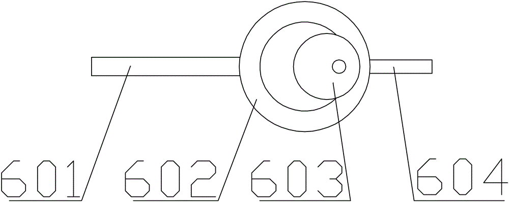
[0069] Such as Figure 5-6 , the locking mechanism adopts a sliding wheel locking mechanism 4, and the sliding wheel locking mechanism 4 includes a locking box 403, and one end of the locking box 403 is fixed on the second clip body 103. On the inner wall, an inclined chute 401 is processed on the inner wall of the lock box 403, and a sliding wheel 405 is installed on the inclined chute 401 through a rotating shaft 402 for sliding fit, and the sliding wheel 405 cooperates with the locking sliding piece 404 The first clamping body 101 and the second clamping body 103 are closed and fixed and locked; the locking sliding piece 404 is fixed on the inner wall of the first clamping body 101 .
[0070] Using the above-mentioned clamping mechanism, in the working process, by inserting the locking sliding piece 404 into the inside of the locking box 403, and then rotating the sliding wheel 405, the sliding wheel 405 slides along the inclined chute 401, and then the sliding wheel 405 U...
PUM
 Abstract
Description
Claims
Application Information
 - R&D
- Intellectual Property
- Life Sciences
- Materials
- Tech Scout
- Unparalleled Data Quality
- Higher Quality Content
- 60% Fewer Hallucinations
Browse by: Latest US Patents, China's latest patents, Technical Efficacy Thesaurus, Application Domain, Technology Topic, Popular Technical Reports.
© 2025 PatSnap. All rights reserved.Legal|Privacy policy|Modern Slavery Act Transparency Statement|Sitemap|About US| Contact US: help@patsnap.com


