A hydraulic disassembly equipment and method specially used for large valves

A valve and hydraulic technology, applied in the field of hydraulic disassembly and assembly equipment for large valves, can solve the problems of inconvenient disassembly of the installation location, high safety risks, and difficulty in replacement, and achieve improved technology and management level, high safety, and production downtime. short effect

Active Publication Date: 2018-11-09
TIANJIN BOHAI PETROCHEM CO LTD
View PDF5 Cites 0 Cited by
  • Summary
  • Abstract
  • Description
  • Claims
  • Application Information

AI Technical Summary

Problems solved by technology

Since the weight of a single body of a super large valve is as high as 22.1 tons, and the overall size is 9100×2000×2280mm, the installation position is very inconvenient to disassemble
Compared with the previous experience of overhauling and replacing smaller valves, it is found that it is very difficult to replace 48-inch extra-large valves using conventional solutions, and there are problems such as low maintenance efficiency, high labor intensity, and high safety risks.
[0003] After searching, no effective technical means to solve the above technical problems has been found, so it is urgent to develop a hydraulic disassembly equipment and method dedicated to large valves that can improve maintenance efficiency and reduce labor intensity

Method used


Image

  • A hydraulic disassembly equipment and method specially used for large valves
  • A hydraulic disassembly equipment and method specially used for large valves
  • A hydraulic disassembly equipment and method specially used for large valves

Examples


Embodiment Construction

[0034] The present invention will be further described in detail below in conjunction with the accompanying drawings and through specific embodiments.

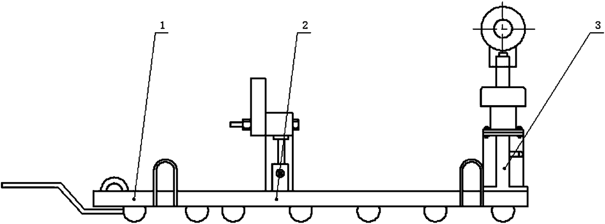
[0035] A hydraulic disassembly and assembly equipment dedicated to large valves, such as figure 1 As shown, it includes a mobile plate assembly 1, an end flange support assembly 2, and a lifting lug hydraulic support assembly 3. The end flange support assembly is installed on one side of the upper part of the mobile plate assembly, and the lifting lug hydraulic pressure The support component supports and fixes the valve through two sets of support components, and the translation of the valve is realized by moving the plate component.

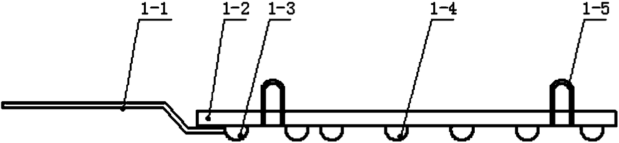
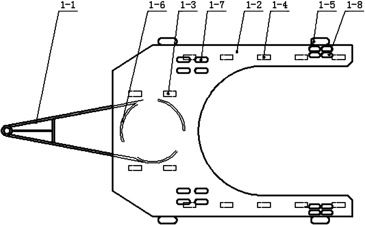
[0036] In this embodiment, the structure of the mobile panel assembly is as follows figure 2 , image 3 As shown, it includes a pallet 1-2 and a traction frame 1-1. The pallet is a U-shaped structure, and its front end is equipped with a traction frame through a slewing support 1-6, and four ...


PUM


Abstract

The invention relates to a special hydraulic dismounting device for a large size valve. The device comprises a moving flat plate assembly, an end flange support assembly and a lifting-lug hydraulic support assembly. The end flange support assembly is mounted at one side of the top of the moving flat plate assembly, and the lifting-lug hydraulic support assembly is mounted at the other side of the moving flat plate assembly. A valve is supported and fixed by means of two groups of support assemblies. The special hydraulic dismounting device for a large size valve achieves the purposes of dismounting, mounting and moving a valve by means of the moving flat plate assembly, the end flange support assembly and the lifting-lug hydraulic support assembly. The end flange support assembly disclosed by the invention operates in a manual hydraulic lifting mode, and is used synchronously with the lifting-lug hydraulic support assembly to achieve the purpose of rising and falling to level and fix a valve. Two manual pumps are used, and single-action jacks are controllable and can achieve self-locking. The special hydraulic dismounting device for a large size valve is simple in structure and scientific and reasonable in design, and can meet the rigid demand of an enterprise for dismounting and mounting ultra-large valves, thus realizing short pipeline shutdown time, high working efficiency, low labor intensity and high safety.

Description

technical field [0001] The invention belongs to the field of petrochemical production, and relates to equipment for maintenance of petrochemical production pipelines, in particular to a hydraulic disassembly equipment and method specially used for large valves. Background technique [0002] At present, during the production of propane dehydrogenation in petrochemical enterprises, many large-inch (such as 48-inch) extra-large valves are installed in the pipelines of the reaction zone of the plant. The service life of the valves is limited. In order to ensure normal production, extra-large valves need to be Replace and repair after running for a certain period of time. Since the weight of a single body of the extra-large valve is as high as 22.1 tons, and the overall size is 9100×2000×2280mm, the installation position is very inconvenient to disassemble. Compared with the previous experience of repairing and replacing smaller valves, it is found that it is extremely difficult...

Claims


Application Information

Patent Timeline
Patent Type & Authority Patents(China)
IPC IPC(8): B23P19/04B66F19/00
CPCB23P19/04B66F19/00
Inventor 秦绪斌李原朱威
Owner TIANJIN BOHAI PETROCHEM CO LTD
Why Eureka
Try Eureka