
Assembling and feeding mechanism of main body part assembling machine for automobile door limiter

A technology of the main part and stopper, applied in the field of assembly and feeding mechanism, can solve the problems of inaccurate feeding position, affecting product quality, increasing production cost, etc., and achieves accurate feeding position, compact structure and high work efficiency Effect

Inactive Publication Date: 2017-06-13
苏州鑫夷斯精密机械有限公司
View PDF0 Cites 10 Cited by
  • Summary
  • Abstract
  • Description
  • Claims
  • Application Information

AI Technical Summary

Problems solved by technology

[0002] The assembly and feeding mechanism is often used in the existing automatic processing and assembly production lines. The assembly and feeding mechanism is to assemble some workpieces together and transport them to the accurate position. However, the existing assembly and feeding mechanism has poor assembly effect. It is easy to cause damage to the workpiece, resulting in waste of resources, and the inaccurate feeding position directly affects the quality of the product, and the work efficiency is low, which increases the production cost. In view of this, it is necessary to modify the main part of the existing automobile door stopper The assembly and feeding mechanism of the assembly machine is improved

Method used


Image

  • Assembling and feeding mechanism of main body part assembling machine for automobile door limiter
  • Assembling and feeding mechanism of main body part assembling machine for automobile door limiter
  • Assembling and feeding mechanism of main body part assembling machine for automobile door limiter

Examples


Embodiment Construction

[0017] The preferred embodiments of the present invention will be described in detail below in conjunction with the accompanying drawings, so that the advantages and features of the invention can be more easily understood by those skilled in the art, so as to define the protection scope of the present invention more clearly.

[0018] see Figure 1 to Figure 8 , the embodiment of the present invention includes:

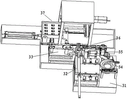
[0019] An assembly and feeding mechanism of an assembly machine for the main part of an automobile door stopper, the assembly and feeding mechanism of the main part assembly machine for an automobile door stopper includes an assembly mounting table 31, and the upper end surface of the assembly mounting table 31 is sequentially fixed with a limit arm The feeding device 32, the stamping device 33 and the movable support feeding recovery device 37, the side of the upper end surface of the assembly installation table 31 located at the limit arm feeding device 32 are succes...


PUM


Abstract

The invention discloses an assembly and feeding mechanism of an assembly machine for the main part of an automobile door limiter. The assembly and feeding mechanism of the assembly machine for the main part of an automobile door limiter includes an assembly and installation platform, and the upper end surface of the assembly and installation platform is sequentially fixed and limited. Positioning arm feeding device, stamping device and movable bracket feeding and recycling device, the upper end surface of the assembly and installation platform is located on one side of the limiting arm feeding device, and the rivet vibrating plate and six-axis manipulator are fixed in sequence, and the rotating end surface of the six-axis manipulator A rivet feeding jaw cylinder is installed, and rivet clips are installed on the clamp arms of the rivet feeding jaw cylinder. The limit arm feeding device and the movable bracket feeding recovery device respectively transport the limit arm and the movable bracket to In the stamping device, at the same time, the cylinder of the rivet feeding jaw on the six-axis manipulator operates so that the two rivet clips can also transport the rivets in the rivet vibrating tray to the stamping device. Through the above method, the present invention has good assembling and feeding effect, high working efficiency and low production cost.

Description

technical field [0001] The invention relates to the field of mechanical automation, in particular to an assembly and feeding mechanism of an assembly machine for the main part of an automobile door stopper. Background technique [0002] The assembly and feeding mechanism is often used in the existing automatic processing and assembly production lines. The assembly and feeding mechanism is to assemble some workpieces together and transport them to the accurate position. However, the existing assembly and feeding mechanism has poor assembly effect. It is easy to cause damage to the workpiece, resulting in waste of resources, and the inaccurate feeding position directly affects the quality of the product, and the work efficiency is low, which increases the production cost. In view of this, it is necessary to modify the main part of the existing automobile door stopper The assembly and feeding mechanism of the assembly machine is improved. Contents of the invention [0003]...

Claims


Application Information

Patent Timeline
IPC IPC(8): B23P19/00B23P19/027
CPCB23P19/001B23P19/006B23P19/027
Inventor 柳斌芳
Owner 苏州鑫夷斯精密机械有限公司
Learn More