Steel ball conveying device

A conveying device and steel ball technology, which is applied in the field of steel ball manufacturing, can solve the problems of oil stains on the steel ball packaging box, easy rusting of steel balls, uneven oil spraying on the surface of steel balls, etc.

Active Publication Date: 2018-10-26
南通壹选智能科技有限公司
View PDF6 Cites 0 Cited by
  • Summary
  • Abstract
  • Description
  • Claims
  • Application Information

AI Technical Summary

Problems solved by technology

[0004] The above patent documents also have the following problems: when the oil is sprayed, the surface of the stee

Method used


Image

  • Steel ball conveying device
  • Steel ball conveying device
  • Steel ball conveying device

Examples


Embodiment Construction

[0026] The present invention will be described in further detail below by means of specific embodiments:

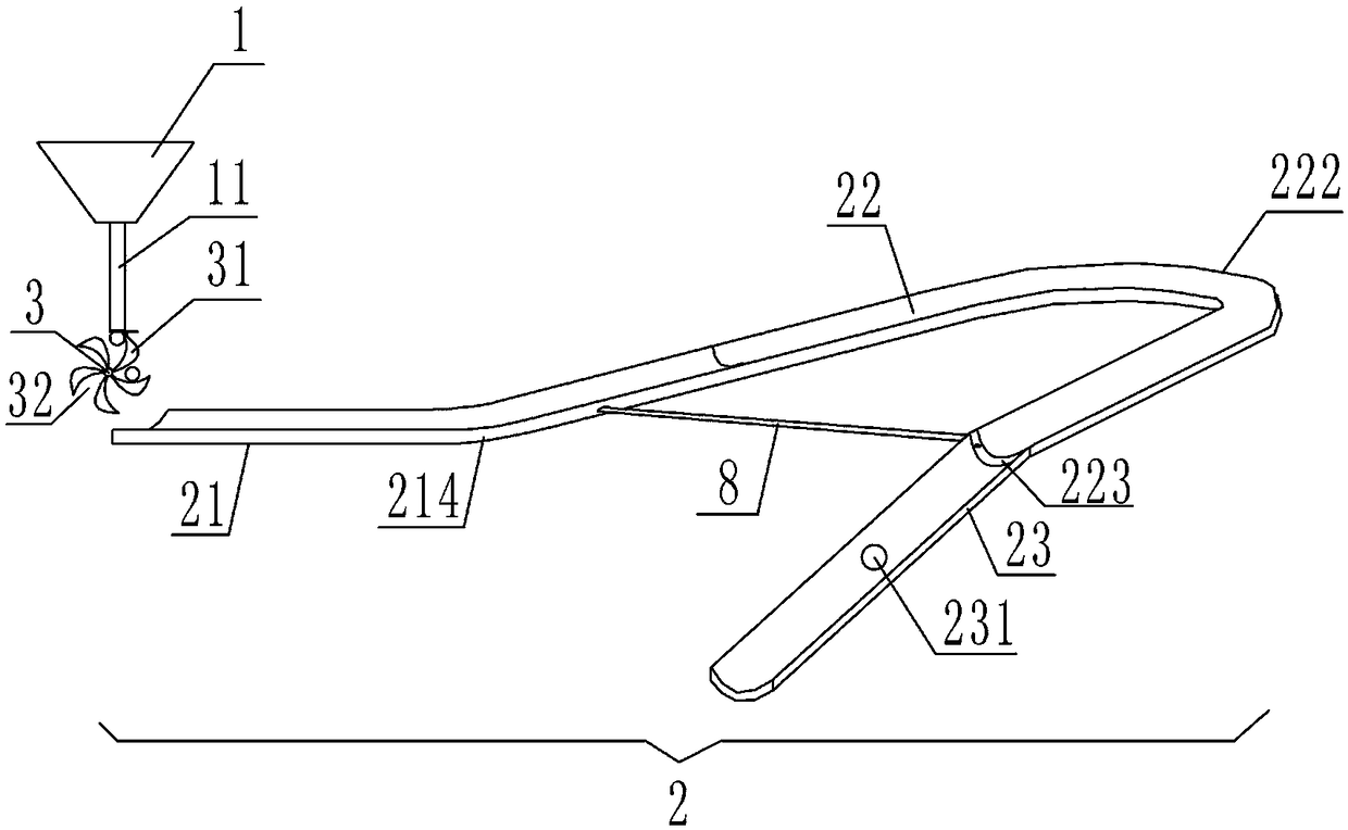
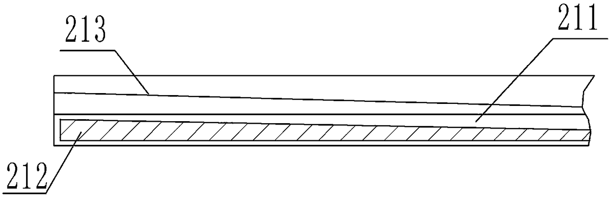
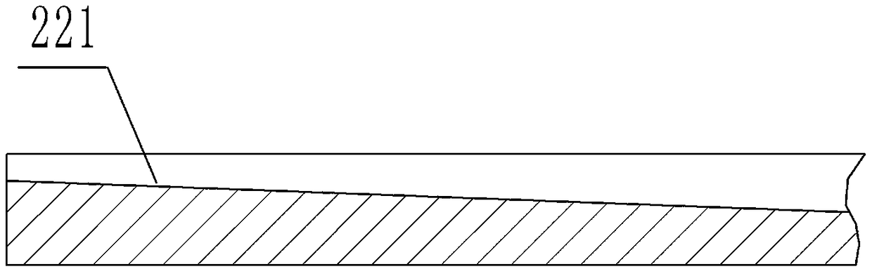
[0027] The reference signs in the accompanying drawings of the description include: charging funnel 1, conveying pipe 11, conveying track 2, oiling section 21, oil chamber 211, sponge layer 212, cotton cloth layer 213, oil chamber track bending part 214, draining oil Section 22, rubber layer 221, oil drain track bending part 222, oil collection chamber 223, screening section 23, screening hole 231, fan-shaped transmission part 3, transmission blade 31, steel ball chamber 32, guide rail 4, retainer 5, spring 6, dial 7, pipeline 8.

[0028] see figure 1 , figure 2 with image 3As shown, the steel ball conveying device includes a charging funnel 1, a conveying track 2 for conveying steel balls, and a fan-shaped conveying part 3 driven by a motor; the lower end of the charging funnel 1 is connected with a conveying pipe 11 that only allows one steel ball to pass through; ...


PUM


Abstract

The invention discloses a steel ball conveying device. The steel ball conveying device comprises a charging hopper, a conveying track for conveying steel balls and a fan-shaped conveying part driven by a motor, wherein the lower end of the charging hopper is connected with a conveying pipe allowing only one steel ball to pass; the fan-shaped conveying part is positioned below the conveying pipe and comprises a plurality of conveying blades; the conveying face of the conveying track is a concave arc surface, and the conveying track is positioned at one side of the fan-shaped conveying part; the conveying track sequentially comprises an oiling section, an oil draining section and a screening section in the conveying direction, an oil cavity is arranged on the oiling section, a spongy layer is arranged in the oil cavity, a cotton cloth layer is arranged above the sponge layer, and two sides of the cotton cloth layer are in detachable connection with the conveying track; an oil cavity track bending part is arranged on the oiling section; a rubber layer is arranged on the oil draining section, two sides of the rubber layer are in detachable connection with the conveying track, and an oil draining track bending part is arranged on the oil draining section; and a screening hole is formed in the screening section. By adoption of the technical scheme, the surfaces of the steel balls can be uniformly oiled in the steel ball screening process.

Description

technical field [0001] The invention relates to the technical field of steel ball manufacturing, in particular to a steel ball conveying device. Background technique [0002] Steel ball is a general term for steel balls, steel segments and special-shaped grinding bodies. From the shape, it can be divided into perfect round ball, capsule ball, ellipse ball, yin and yang ball, hollow ball, multi-faceted ball, multi-missing ball and so on. Steel ball production methods generally include forging, rolling, semi-solid forming and casting. After the steel ball is processed, the anti-rust of the steel ball is currently done by the staff manually spraying the anti-rust oil. This method of oiling is not easy to control, and the steel ball is often rusted due to uneven oiling; and The packaging of steel balls on the market is to manually put the steel balls into boxes for packaging, which is not only cumbersome but also inefficient. [0003] Chinese patent authorization announcement...

Claims


Application Information

Patent Timeline
IPC IPC(8): B05C1/06B05C13/02B05C11/02B05C11/10
CPCB05C1/06B05C11/02B05C11/1039B05C13/02
Inventor 苏祖弟
Owner 南通壹选智能科技有限公司
Why Eureka
Try Eureka