Rear-axle assembly with overlapping of torsion-beam main beam, upper-plate side beam and lower-plate side beam and manufacture method thereof

A side beam and torsion technology, applied in the field of vehicle parts manufacturing, can solve problems such as weak anti-rolling ability, mutual influence, and limited comfort, and reduce excessive local stress, small vertical positive and negative deviations, and complex processes The effect of reducing

Pending Publication Date: 2017-06-09
ZHEJIANG TUOWEI AUTOMOBILE PARTS CO LTD
View PDF0 Cites 0 Cited by
  • Summary
  • Abstract
  • Description
  • Claims
  • Application Information

AI Technical Summary

Problems solved by technology

[0005] However, the suspension system of the semi-independent structure also has the following disadvantages: poor load-bearing performance, weak anti-rolling ability, poor shock absorption performance, and limited comfort
The torsional beam generates torsional stress and shear stress, and there is a higher stress at the welded joint, which allows the load on the rear bearing to be limited by the strength of the torsion beam; in order to ensure driving stability, the joint points of the elastic bushings of the longitudinal swing arms on both sides are stressed Complicated; the wheels on both sides interact with each other; poor comfort; constantly carry out extreme design, eliminate various stresses caused by load bearing, and disperse stress, which is the shortcoming we have been trying to overcome

Method used


Image

  • Rear-axle assembly with overlapping of torsion-beam main beam, upper-plate side beam and lower-plate side beam and manufacture method thereof
  • Rear-axle assembly with overlapping of torsion-beam main beam, upper-plate side beam and lower-plate side beam and manufacture method thereof
  • Rear-axle assembly with overlapping of torsion-beam main beam, upper-plate side beam and lower-plate side beam and manufacture method thereof

Examples


Embodiment Construction

[0035] Below by embodiment, in conjunction with accompanying drawing, technical scheme of the present invention is described further in detail:

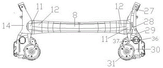
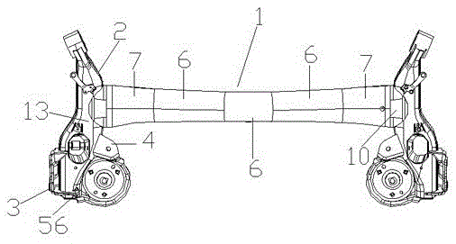
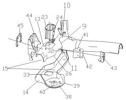
[0036] like Figure 1-6 As shown, a preparation method of a torsion beam main beam and a rear axle assembly with upper and lower plate side beams includes:

[0037] Step 1: Use hydroforming technology to make large-diameter sealed main girder round tubes with thin metal plates, and then use water-expansion forming and stretching to make U-shaped cross-section reinforced structural grooves at the bottom of the main girder of large-diameter sealed main girder tubes , make use of the large-diameter sealed main beam characteristics of the main beam itself to make side beam lap connection ports with a large cross-sectional perimeter at both ends of the nozzle and pipe tail;

[0038] Step 2: Use two unconnected metal plates to make the upper plate of the side beam and the lower plate of the side beam respectively. The forming shape is a c...


PUM


Abstract

The invention relates to the field of vehicle parts manufacturing, in particular to a rear axle assembly with a torsion beam main girder and upper and lower plate side girders. The object of the present invention is to design a rear axle assembly in which the torsion beam main girder overlaps the upper and lower plate side girders, mainly to overcome the prior art and to manufacture and design a longitudinal arm torsion beam suspension using hydraulic forming The torsion beam cancels the original reinforcing plate, and the side beams are made of sheet metal on the upper plate and the lower plate respectively. The present invention is a rear with torsion beam main beam and upper and lower plate side beams realized through the following technical scheme. The bridge assembly includes the main girder, the side girder, the wheel connection mounting plate, and the auxiliary spring mounting bracket; the main girder is a closed girder, and the bottom of the main girder is provided with a U-shaped section reinforcement groove as a whole, and the main girder is occluded and connected to the side girder. The main beam is connected to the side beam, and the left side beam or the right side beam includes a side beam upper plate and a side beam lower plate, and the side beam upper plate and the side beam lower plate cover each other to form a side beam cavity.

Description

technical field [0001] The invention relates to the field of vehicle parts manufacturing, in particular to a preparation method for a rear axle assembly with a torsion beam main girder and upper and lower plate side beams and the rear axle assembly with the torsion beam main girder overlapping the upper and lower plate side girders. to make. Background technique [0002] The car is one of the modern technologies that we cannot live without. It facilitates our transportation and road traffic, and the torsion beam suspension in the chassis is a type of rear suspension of the car, which is balanced by a torsion beam The left and right wheels jump up and down to reduce the shaking of the vehicle and keep the vehicle stable. Although some manufacturers claim that their cars are equipped with a torsion beam semi-independent suspension, the torsion beam is still a type of non-independent suspension. The torsion beam has an independent suspension. Type torsion beam and non-independ...

Claims


Application Information

Patent Timeline
Patent Type & Authority Applications(China)
IPC IPC(8): B60G21/055B60G13/04
CPCB60G21/055B60G13/04B60G2206/81
Inventor 刘黎明邓东东徐晶杨天洪
Owner ZHEJIANG TUOWEI AUTOMOBILE PARTS CO LTD
Why Eureka
Try Eureka