
Laser processing system of brittle material base plate

A brittle material substrate and laser processing technology, which is applied in laser welding equipment, metal processing equipment, manufacturing tools, etc., can solve the problems of low processing efficiency, high error rate, labor and material resources, etc., to improve production efficiency and product accuracy, The effect of high production quality and reduced error rate

Active Publication Date: 2017-06-09
南京魔迪多维数码科技有限公司
View PDF6 Cites 6 Cited by
  • Summary
  • Abstract
  • Description
  • Claims
  • Application Information

AI Technical Summary

Problems solved by technology

[0002] At present, more and more manufacturers are using components such as substrates formed by two-dimensional or three-dimensional processing technology in electronic equipment, and with the increase of industrial and social needs, high-precision and high-quality brittle materials such as glass or crystal Two-dimensional or three-dimensional parts processed are becoming more and more popular; however, most of the traditional manufacturing industries use a combination of numerical control, wire saw technology and grinding lathes to complete the processing and manufacturing of these parts. The efficiency is low, the processing procedures are numerous and complicated, and the general processing factory needs hundreds of machines to process the above parts, so it is very labor-intensive and material resources
[0003] At present, although there are laser processing methods for brittle materials in the existing technology, the existing methods are limited to the manufacture and processing of two-dimensional parts, and cannot process three-dimensional parts, and the processing quality of parts in the prior art is low. , It takes a long time to process a part, the product has low precision and high error rate and other defects

Method used


Image

  • Laser processing system of brittle material base plate
  • Laser processing system of brittle material base plate
  • Laser processing system of brittle material base plate

Examples


Embodiment Construction

[0048] The following will clearly and completely describe the technical solutions in the embodiments of the present invention with reference to the accompanying drawings in the embodiments of the present invention. Obviously, the described embodiments are only some, not all, embodiments of the present invention. The components of the embodiments of the invention generally described and illustrated in the figures herein may be arranged and designed in a variety of different configurations. Accordingly, the following detailed description of the embodiments of the invention provided in the accompanying drawings is not intended to limit the scope of the claimed invention, but merely represents selected embodiments of the invention. Based on the embodiments of the present invention, all other embodiments obtained by those skilled in the art without making creative efforts belong to the protection scope of the present invention.

[0049] Such as figure 1 In the illustrated embodime...


PUM

PropertyMeasurementUnit
poweraaaaaaaaaa

Abstract

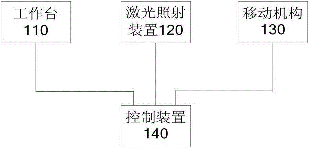
The invention provides a laser processing system of a brittle material base plate. The system comprises a working table, a laser irradiation device, a moving mechanism and a control device, wherein the working table is used for carrying the brittle material base plate; the laser irradiation device is used for performing laser irradiation on the brittle material base plate according to the preset laser irradiation conditions; the moving mechanism is used for making the working table move according to a specific moving track; and the control device is used for forming a virtual part according to the preset parameters of a final to-be-formed part of the brittle material base plate, showing and storing the virtual part and controlling processing of the brittle material base plate according to the stored virtual part. By means of the laser processing system of the brittle material base plate, processing of two-dimensional or three-dimensional parts of the brittle material can be achieved, the production quality is high, and the positive effects of saving time and reducing error rate are achieved.

Description

technical field [0001] The invention relates to the technical field of laser processing, in particular to a laser processing system for a brittle material substrate. Background technique [0002] At present, more and more manufacturers are using components such as substrates formed by two-dimensional or three-dimensional processing technology in electronic equipment, and with the increase of industrial and social needs, high-precision and high-quality brittle materials such as glass or crystal Two-dimensional or three-dimensional parts processed are becoming more and more popular; however, most of the traditional manufacturing industries use a combination of numerical control, wire saw technology and grinding lathes to complete the processing and manufacturing of these parts. The efficiency is low, the processing procedures are various and complicated, and the general processing factory needs hundreds of machines to process the above-mentioned parts, so it is very labor-inte...

Claims


Application Information

Patent Timeline
Patent Type & Authority Applications(China)
IPC IPC(8): B23K26/38B23K26/70B23K26/40
CPCB23K26/38B23K26/40
Inventor 洪觉慧施瑞
Owner 南京魔迪多维数码科技有限公司
Learn More