
High-frequency oscillating wave capacitance method oil leakage detection and alarm device

A leakage detection and high-frequency oscillation technology, which is applied in the field of oil leakage alarm, can solve the problems of increasing the workload of the staff, not being able to find it in time, and the astonishingly high price, so as to achieve safe and reliable detection results, improve detection accuracy, and improve stability sexual effect

Pending Publication Date: 2017-06-06
PINGDINGSHAN SHENMA WANLI CHEM
View PDF7 Cites 0 Cited by
  • Summary
  • Abstract
  • Description
  • Claims
  • Application Information

AI Technical Summary

Problems solved by technology

[0002] During the use of the oil storage tank, if the welding process of the oil storage tank is not up to standard, there is a risk of oil leakage in the oil storage tank. The leaked oil not only pollutes the environment, but also easily causes fire accidents, which is harmful to personal and property safety. cause huge losses
[0003] Existing oil sealing devices are generally inspected by personnel on a regular basis, but manual inspection will inevitably have loopholes, which not only increases the workload of the staff, but also has poor inspection results, especially the traces of oil storage tanks cannot be found in time Leakage phenomenon
At the same time, regular inspections also have time loopholes, and leakage accidents that occur during the inspection cycle cannot be discovered in time
[0004] At present, the detection of oil storage tanks generally adopts ultrasonic detection technology. This detection method has high detection accuracy, but the price is also surprisingly high, which is completely unsuitable for the current application requirements of our country.

Method used


Image

  • High-frequency oscillating wave capacitance method oil leakage detection and alarm device
  • High-frequency oscillating wave capacitance method oil leakage detection and alarm device
  • High-frequency oscillating wave capacitance method oil leakage detection and alarm device

Examples


Embodiment Construction

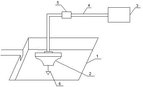
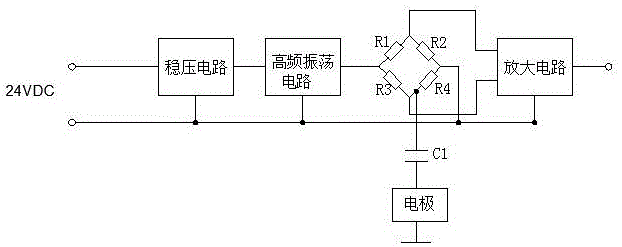
[0025] Such as Figure 1 to Figure 3 As shown, the present invention includes a water tank 1, a detector 2 and a converter 3. The water tank 1 is arranged at a low point in the tank area of ​​the oil storage tank to ensure that the leaked oil and sundries can flow into the water tank 1, and the detector 2 is arranged on the water surface Above, the signal output end of the detector 2 is connected to the signal input end of the converter 3 through the cable 4. In this embodiment, the detector 2 and the converter 3 are connected through the junction box 5 through the cable 4, and the detector 2 The power supply end is connected to the power supply through the converter 3, the detector 2 is used to detect oil leakage, and is input to the converter 3 through the cable 4, and the converter 3 is used to process the signal detected by the detector 2 to judge whether oil leakage occurs .

[0026] The detector 2 includes a casing and a detection circuit arranged in the casing. The det...


PUM


Abstract

The invention discloses a high-frequency oscillating wave capacitance method oil leakage detection and alarm device comprising a water tank, a detector and a converter. The water tank is arranged at the low position of the tank field of an oil storage tank. The detector is arranged on the water surface. The signal output end of the detector is connected with the signal input end of the converter through a cable. The power supply end of the detector is connected with a power supply through the converter. The detector comprises a shell and a detection circuit arranged in the shell. An electrode is arranged on the detection circuit. The upper end of the electrode is connected in series with the detection circuit, and the lower end is arranged under the water surface. The converter comprises a shell and a conversion circuit arranged in the shell. The input end of the conversion circuit is connected with the output end of the detection circuit. The output end of the conversion circuit is connected with an alerter. The phenomenon of oil leakage can be accurately detected in real time and alarming can be performed so as to be safe and reliable.

Description

technical field [0001] The invention relates to the technical field of oil leakage alarms, in particular to a high-frequency oscillatory wave capacitance method oil leakage detection and alarm device. Background technique [0002] During the use of the oil storage tank, if the welding process of the oil storage tank is not up to standard, there is a risk of oil leakage in the oil storage tank. The leaked oil not only pollutes the environment, but also easily causes fire accidents, which is harmful to personal and property safety. cause huge losses. [0003] Existing oil sealing devices are generally inspected by personnel on a regular basis, but manual inspection will inevitably have loopholes, which not only increases the workload of the staff, but also has poor inspection results, especially the traces of oil storage tanks cannot be found in time Leakage phenomenon. At the same time, regular inspections also have time loopholes, and leakage accidents that occur during th...

Claims


Application Information

Patent Timeline
Patent Type & Authority Applications(China)
IPC IPC(8): G01M3/16
CPCG01M3/186
Inventor 刘国良王留栓魏新军宁红军魏坤赵东黄尚国李迎春吴向红李金友王延春林景延高广丽牛永森王晋李可张永利王俊涛郝丽娟刘延超闫晓浩吕洋李申王麦见马子峰宁永亮鄂志马希平贾亚平刘丽秋余跃平鲁来勇徐付来李振江刘宏伟冯李静许明先张保贵张永涛张腾周旺召魏帅
Owner PINGDINGSHAN SHENMA WANLI CHEM
Learn More