Joint movement assist device
A joint movement and auxiliary device technology, applied in passive exercise equipment, physical therapy, etc., to achieve the effect of light weight
- Summary
- Abstract
- Description
- Claims
- Application Information
AI Technical Summary
Problems solved by technology
Method used
Image
Examples
no. 1 approach
[0068] First, refer to Figure 3 to Figure 15 A first embodiment of the present invention will be described.
[0069]
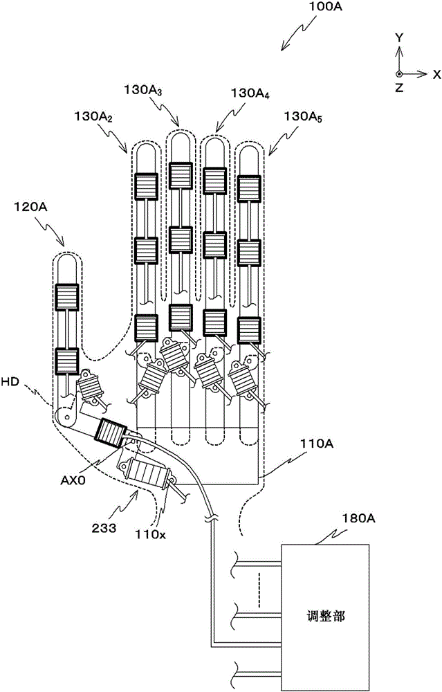
[0070] exist image 3 , Figure 4 An external view of the joint motion assisting device 100A according to the first embodiment is shown in FIG. image 3 , Figure 4 The coordinate system (X, Y, Z) in is the following coordinate system: when all fingers are closed, the direction perpendicular to the extending direction of the fingers and from the thumb (first finger) to the little finger (fifth finger) is used as In the +X direction, the direction from the wrist toward the fingertips is referred to as the +Y direction, and the direction from the palm side toward the back of the hand is referred to as the +Z direction.
[0071] here, image 3 This is an external view of the articulation assisting device 100A worn on the back of the hand (back of the hand) of the right hand HD as viewed from the back of the hand (back of the hand) when the joints of the f...
no. 2 approach
[0234] Below, the main reference Figure 16 to Figure 18 A second embodiment of the present invention will be described.
[0235]
[0236] Figure 16 An external view of an articulation assisting device 100B according to the second embodiment is shown in FIG. here, Figure 16 This is an external view of the joint motion assisting device 100B worn on the back of the right hand HD when the joints of the fingers are in the extended state and the fingers are in the closed state, viewed from the back of the hand.
[0237] like Figure 16 As shown, the joint motion assisting device 100B is different from the above-described first embodiment in that it includes a carpal member 110B instead of the carpal member 110A, and a finger joint assisting portion 130B. j (j=2, . . . , 5) in place of the finger joint motion assisting portion 130A j (j=2, . . . , 5); and an adjustment unit 180B is provided instead of the adjustment unit 180A. The following description will focus mainly on...
no. 3 approach
[0290] Below, the main reference Figure 19 to Figure 23 A third embodiment of the present invention will be described.
[0291]
[0292] Figure 19 , 20 An external view of an articulation assisting device 100C of a third embodiment is shown in FIG. here, Figure 19 This is an external view of the joint motion assisting device 100C worn on the back of the right hand HD when the joints of the fingers are in the extended state and the fingers are in the closed state, viewed from the back of the hand. also, Figure 20 viewed from the palm side Figure 19 An external view of the illustrated joint motion assisting device 100C. In addition, in Figure 20 , the illustration of the right hand wearing the joint motion assisting device 100C is omitted.
[0293] like Figure 19 , Figure 20 In summary, compared with the articulation assisting device 100A according to the first embodiment described above, the articulation assisting device 100C is different in that it includes...
PUM
 Abstract
Description
Claims
Application Information
 - R&D Engineer
- R&D Manager
- IP Professional
- Industry Leading Data Capabilities
- Powerful AI technology
- Patent DNA Extraction
Browse by: Latest US Patents, China's latest patents, Technical Efficacy Thesaurus, Application Domain, Technology Topic, Popular Technical Reports.
© 2024 PatSnap. All rights reserved.Legal|Privacy policy|Modern Slavery Act Transparency Statement|Sitemap|About US| Contact US: help@patsnap.com


