
Visible light communication distributed light source position optimization method based on fireworks algorithm

A technology of visible light communication and distributed light source, which is applied in the field of position optimization of distributed light source for visible light communication based on fireworks algorithm, which can solve the problems that the total number of LED light sources cannot be set arbitrarily, and there is no research on the distribution optimization of LED light sources.

Inactive Publication Date: 2017-05-31
XUZHOU NORMAL UNIVERSITY
View PDF6 Cites 5 Cited by
  • Summary
  • Abstract
  • Description
  • Claims
  • Application Information

AI Technical Summary

Problems solved by technology

[0004] The problems in the above design methods are: First, most of the research on the distribution of LED light sources in visible light communication at home and abroad is the distribution of LED light sources in a uniform array, or is limited to the layout of adding LED light sources to the four corners where the optical signal SNR is extremely weak , and the layout of increasing the power of the LED light source for the extremely weak SNR of the surrounding edge light signal, there is no optimization study on the distribution of the LED light source
Third, the total number of LED light sources cannot be set arbitrarily. For a communication space with equal length and width, the number of LED light sources is usually N 2 , for example 2 2 , that is, 4 LED light sources, 4 2 , that is, 16 LED light sources

Method used


Image

  • Visible light communication distributed light source position optimization method based on fireworks algorithm
  • Visible light communication distributed light source position optimization method based on fireworks algorithm
  • Visible light communication distributed light source position optimization method based on fireworks algorithm

Examples


Embodiment Construction

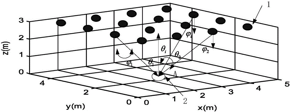
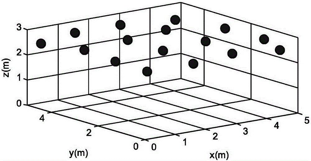
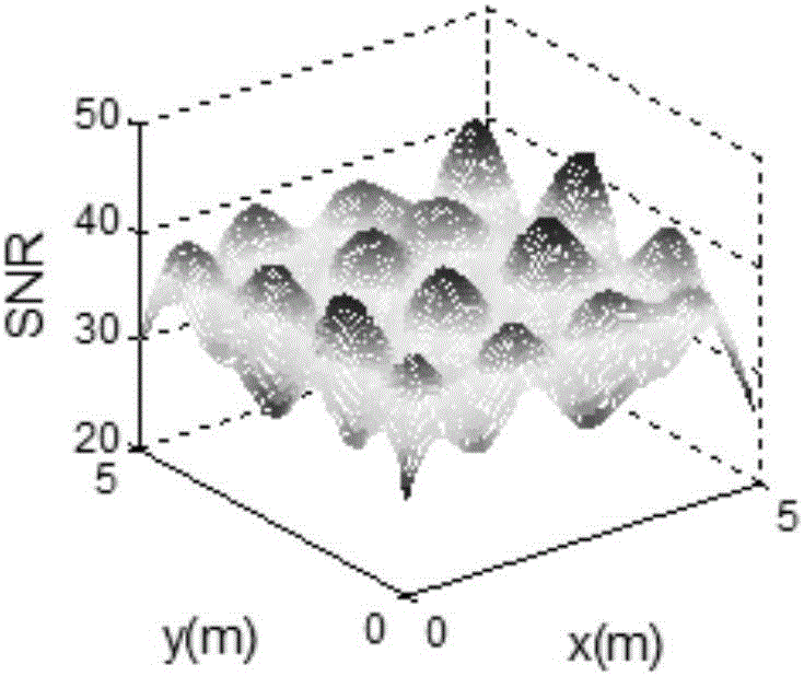
[0060] The present invention constructs the signal-to-noise ratio of the received optical signal and the signal-to-noise ratio factor calculation model of the receiving plane by constructing multi-point LED light sources in the visible light communication space as emission points; in a communication space with a certain length, width and height, a certain number of LED light sources with equal power In the space, apply the fireworks algorithm to find the three-dimensional position of the LED light source that makes the signal-to-noise ratio distribution of the optical signal received by the receiving plane the most uniform; on this basis, considering that the height of the LED light source in some communication spaces can be adjusted within the allowable range, apply the fireworks The algorithm finds the three-dimensional position of each LED light source, so that the signal-to-noise ratio distribution of the received planar light signal is the most uniform, and the optimal comm...


PUM


Abstract

The invention provides a visible light communication distributed light source position optimization method based on a fireworks algorithm. Through building a calculation model for a signal-to-noise ratio of receiving optical signals and a signal-to-noise ratio factor of a receiving plane with multiple points of LED light sources as transmission points in the visible light communication space, a certain number of LED light sources with the same power are placed in the communication space with a fixed length, a width and a height, a fireworks algorithm is used for finding an LED light source three-dimensional position with the most uniform signal-to-noise ratio distribution for optical signals received by the receiving plane, SNR fluctuation can be reduced effectively, an SNR mean value is improved, the signal-to-noise ratio distribution for the optical signals on the receiving plane is the most uniform, the optimal communication effects and the optimal lighting effects can be achieved, and users at different positions can be ensured to receive signals with the consistent communication quality in a maximal area mode.

Description

technical field [0001] The invention relates to the field of visible light communication, in particular to a position optimization method for distributed light sources of visible light communication based on fireworks algorithm. Background technique [0002] Visible light communication uses light-emitting diodes to transmit and receive devices with simple, fast transmission speed, low bit error rate, and weak multipath interference phenomenon. It provides high-efficiency and energy-saving communication while lighting. The area that can be illuminated by light is the visible light communication area, and the area without light irradiation does not exist. For data communication, the data cannot pass through thick objects such as walls or curtains, and the data confidentiality is high. Visible light communication systems often use intensity modulation-direct detection to realize data communication, and directly detect the optical signal emitted by the LED directly detected by t...

Claims


Application Information

Patent Timeline
IPC IPC(8): H04B10/116H04B10/50
CPCH04B10/116H04B10/502
Inventor 游春霞颜栋魏明生黄智
Owner XUZHOU NORMAL UNIVERSITY
Learn More