
New energy air force station sending out circuit pilot protection method based on current wave form similarity

A technology of sending out lines and current waveforms, which is applied in the field of longitudinal protection of outgoing lines of new energy stations based on the similarity of current waveforms, which can solve the problems of sensitivity, rapidity reduction, and false refusal to operate, and achieve reliability and sensitivity. High performance and good quickness

Active Publication Date: 2017-05-31
NORTH CHINA ELECTRIC POWER UNIV (BAODING)
View PDF4 Cites 34 Cited by
  • Summary
  • Abstract
  • Description
  • Claims
  • Application Information

AI Technical Summary

Problems solved by technology

However, new energy sources such as wind turbines and photovoltaic cells are different from synchronous generators in terms of power generation principles, control methods, and grid connection methods. The short-circuit current characteristics provided by new energy stations are completely different from those of traditional synchronous generators. Differential protection and distance protection Sensitivity and quick action decrease when traditional relay protection is applied to sending lines
Moreover, with the increasing scale of new energy power sources connected to the grid, these traditional protections are still facing the risk of false refusal.

Method used


Image

  • New energy air force station sending out circuit pilot protection method based on current wave form similarity
  • New energy air force station sending out circuit pilot protection method based on current wave form similarity
  • New energy air force station sending out circuit pilot protection method based on current wave form similarity

Examples


Embodiment Construction

[0024] The technical solutions in the embodiments of the present invention will be clearly and completely described below in conjunction with the accompanying drawings in the embodiments of the present invention. Obviously, the described embodiments are only some of the embodiments of the present invention, not all of them. Based on the embodiments of the present invention, all other embodiments obtained by persons of ordinary skill in the art without making creative efforts belong to the protection scope of the present invention.

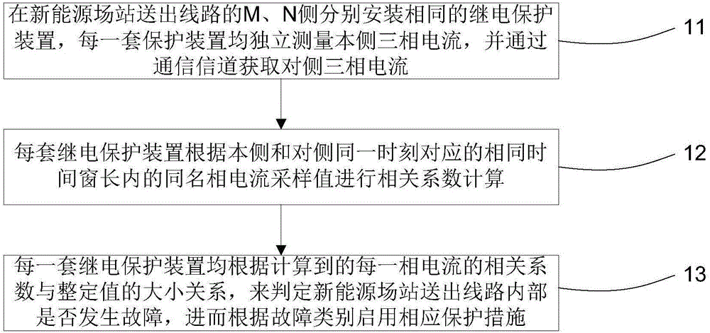
[0025] figure 1 It is a flow chart of the method for longitudinal protection of new energy station sending lines based on the similarity of current waveform provided by the embodiment of the present invention. Such as figure 1 As shown, it mainly includes the following steps:

[0026] Step 11. Install the same relay protection device on the M and N sides of the outgoing line of the new energy station. Each set of protection devices independently ...


PUM


Abstract

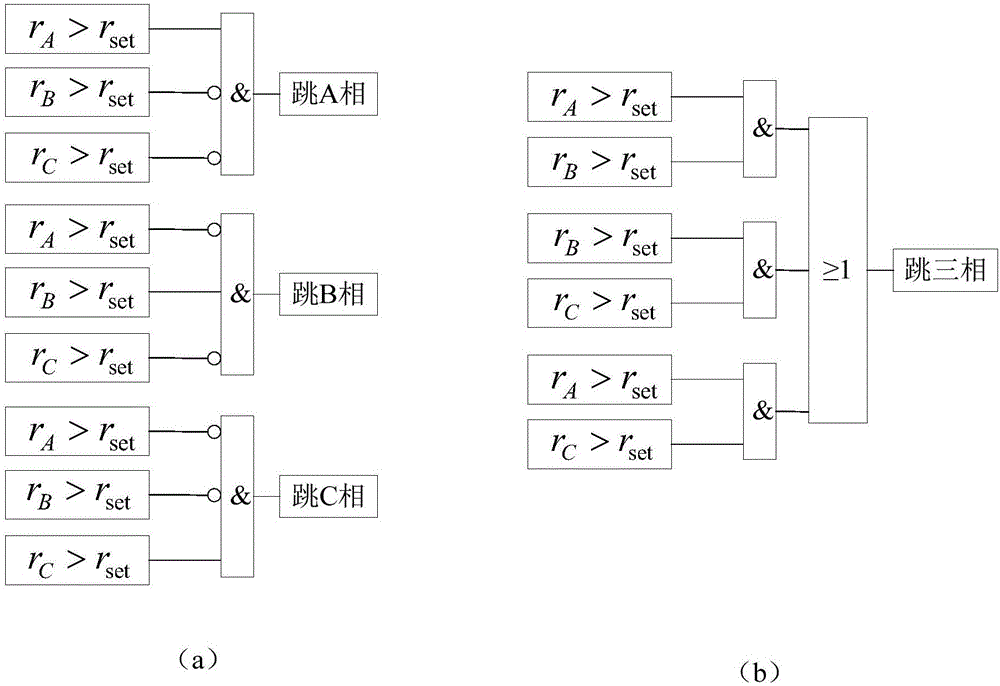
The invention discloses a new energy air force station sending out circuit pilot protection method based on current wave form similarity. The method comprises the steps that same relay protection devices are installed at the M and N sides of a new energy air force station sending out circuit, wherein each suit of the protection devices independently measures a three-phase current at the side each suit of the protection devices is installed and obtains the three-phase current of the opposite side through a communication channel; each suit of the relay protection devices conducts relevant coefficient calculation according to same name phase current sampling values which correspond to the same moment in a same time window length of the side each of the protection devices is installed and the opposite side; each suit of the relay protection devices judges whether or not default occurs in the inner part of the new energy air force station sending out circuit according to the size relationship between the calculated relevant coefficient of each phase current and a setting value so as to start corresponding protection measures according to the types of the default. The method can provide new principle pilot protection of which the reliability and sensitivity are high and the power sing is good for the new energy air force station sending out circuit of different types and different capacity sizes.

Description

technical field [0001] The invention relates to the field of relay protection of new energy power systems, in particular to a method for longitudinal protection of sending lines of new energy stations based on the similarity of current waveforms. Background technique [0002] In my country, large-scale and clustered access to the power grid is one of the main ways to utilize new energy sources such as wind power and photovoltaics. Large-scale new energy stations have large power generation capacity and are often connected to the power grid through special high-voltage transmission lines. When the power grid fails, in order to improve the efficiency of new energy utilization and ensure the safe and stable operation of the system, the new energy power supply should not be easily disconnected from the grid. For this reason, reliable relay protection of the power grid is required to quickly remove the fault. As the key channel for power transmission of large-scale new energy st...

Claims


Application Information

Patent Timeline
IPC IPC(8): H02H7/26
CPCH02H7/26H02H3/30G01R31/086Y04S10/52
Inventor 毕天姝李彦宾贾科杨奇逊
Owner NORTH CHINA ELECTRIC POWER UNIV (BAODING)
Learn More