Link fitting and converter station with same

A technology for connecting metal fittings and fittings, applied in the field of converter stations, can solve problems such as large force on equipment terminals, and achieve the effect of ensuring service life

Pending Publication Date: 2017-05-31
STATE GRID CORP OF CHINA +4
View PDF6 Cites 5 Cited by
  • Summary
  • Abstract
  • Description
  • Claims
  • Application Information

AI Technical Summary

Problems solved by technology

[0004] The purpose of the present invention is to provide a connecting fitting to solve the problem in the prior art that the elastic force of the conductor ...

Method used


Image

  • Link fitting and converter station with same
  • Link fitting and converter station with same
  • Link fitting and converter station with same

Examples


Embodiment Construction

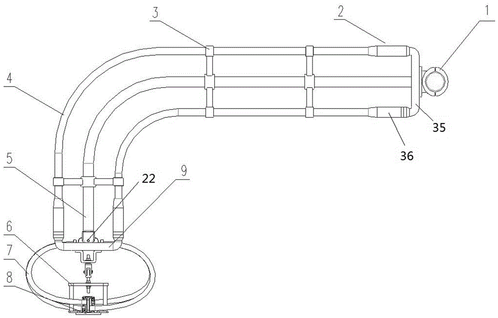
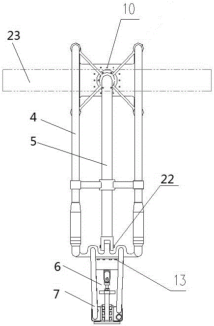
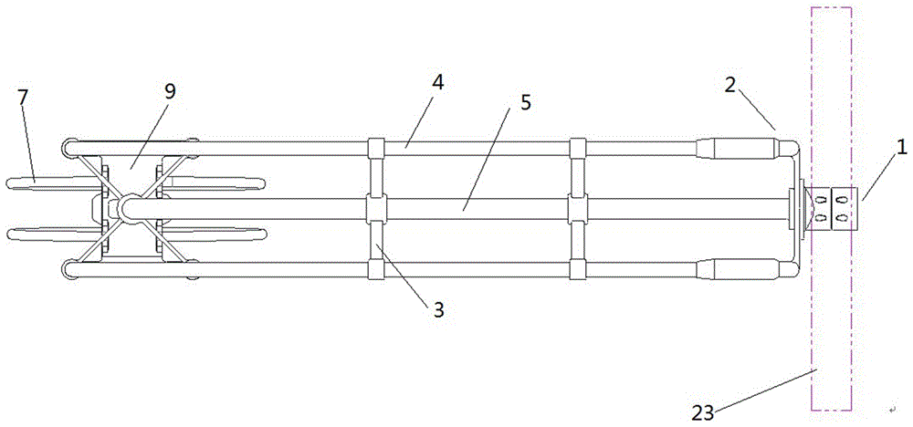
[0041] Embodiment 1 of the converter station is as Figure 1~8As shown: It includes a converter transformer and a capacitor. The equipment terminal of the converter transformer, that is, the outlet bushing on the grid side, is connected to the equipment terminal 23 of the capacitor through connecting fittings. The equipment terminal 23 of the capacitor is a tube mother structure. The connecting fittings include conductors and fitting supports arranged along the arrangement direction of the conductors. The conductors include four split wires 4 evenly distributed along the circumferential direction. The fitting supports include support rods 5 arranged between the split wires. The support rods 5 are aluminum alloy tubes , the split wire 4 is connected to the support rod 5 through the connecting structure. Both the split wire 4 and the hardware support are L-shaped structures with short sides and long sides, the short sides are vertically arranged, and the long sides are arranged ...


PUM


Abstract

The invention relates to a link fitting and a converter station with the same. The link fitting comprises a conductor and a fitting support, wherein the conductor is used for implementing electrical connection among corresponding devices and is connected to the fitting support through a connecting structure, and the fitting support is disposed among the devices in a conductor extension direction during use. The link fitting has the advantage that the link fitting comprises the fitting support disposed among the corresponding devices during use and the conductor connected to the fitting support through the connecting structure, and the fitting support is used for bearing elasticity of leads, so that the problem that service life of device thermals is affected due to the fact that the elasticity of the leads act on the device terminals completely is avoided.

Description

technical field [0001] The invention relates to a connecting fitting in the field of electric power transmission and a converter station using the connecting fitting. Background technique [0002] In the UHV converter station, the connection between the grid-side outlet bushing of the converter transformer and the RI capacitor generally adopts JLHN58K-1600 and other large-diameter conductors. The connection distance between the transformer and the RI capacitor is relatively short, and the wires need to be bent and pre-arched during equipment installation. Due to the error of manufacturing accuracy, such wires with larger diameters will generate greater installation stress on the equipment terminals. The bending stress and extrusion stress of the wire are relatively large, and the force transmitted to the equipment terminals at both ends is relatively large, resulting in deformation of the corresponding equipment terminals, and even rupture accidents. In addition, during nor...

Claims


Application Information

Patent Timeline
IPC IPC(8): H01R11/01
CPCH01R11/01H01R2201/22
Inventor 郭贤珊刘杰乐波祝全乐付颖常林晶李俊辉张炜郭银峰宋铁创徐健涛曾维雯周春雨
Owner STATE GRID CORP OF CHINA
Why Eureka
Try Eureka