
Fuse protector and fuse protector base thereof

A fuse and fuse link technology, applied in electrical components, circuits, emergency protection devices, etc., can solve the problems of dimensional deviation, defective products, and high rework rate, and achieve the effect of reducing processing accuracy and improving stability.

Active Publication Date: 2017-05-31
ZHEJIANG XINLI FUSE
View PDF5 Cites 2 Cited by
  • Summary
  • Abstract
  • Description
  • Claims
  • Application Information

AI Technical Summary

Problems solved by technology

[0003] Although the existing above-mentioned fuses have good performance, they have very strict requirements on the manufacturing process, which is mainly reflected in that: the above-mentioned fuses are arranged to interfere with both ends of the fuse body by setting the base contacts corresponding to the wiring components, and the base contacts It is in point contact with both ends of the fuse. When manufacturing the fuse base, it is necessary not only to ensure the accuracy of the installation position of the base contacts, but also to ensure the accuracy of the length of the fuse. The error is usually required to be controlled within plus or minus 0.3mm, which is the industry standard. The internal level is relatively high, and a fuse base of one specification can only be used for one type of fuse; the point is that the fuse and base contacts in the fuse are set for multiple sets of superposition, as long as there is one fuse Or the dimensional deviation of the base contact will lead to poor contact of the entire fuse, resulting in defective products and a high rework rate; this problem is a problem that plagues downstream manufacturers

Method used


Image

  • Fuse protector and fuse protector base thereof
  • Fuse protector and fuse protector base thereof
  • Fuse protector and fuse protector base thereof

Examples


Embodiment Construction

[0034] The present invention will be described in further detail below in conjunction with the accompanying drawings.

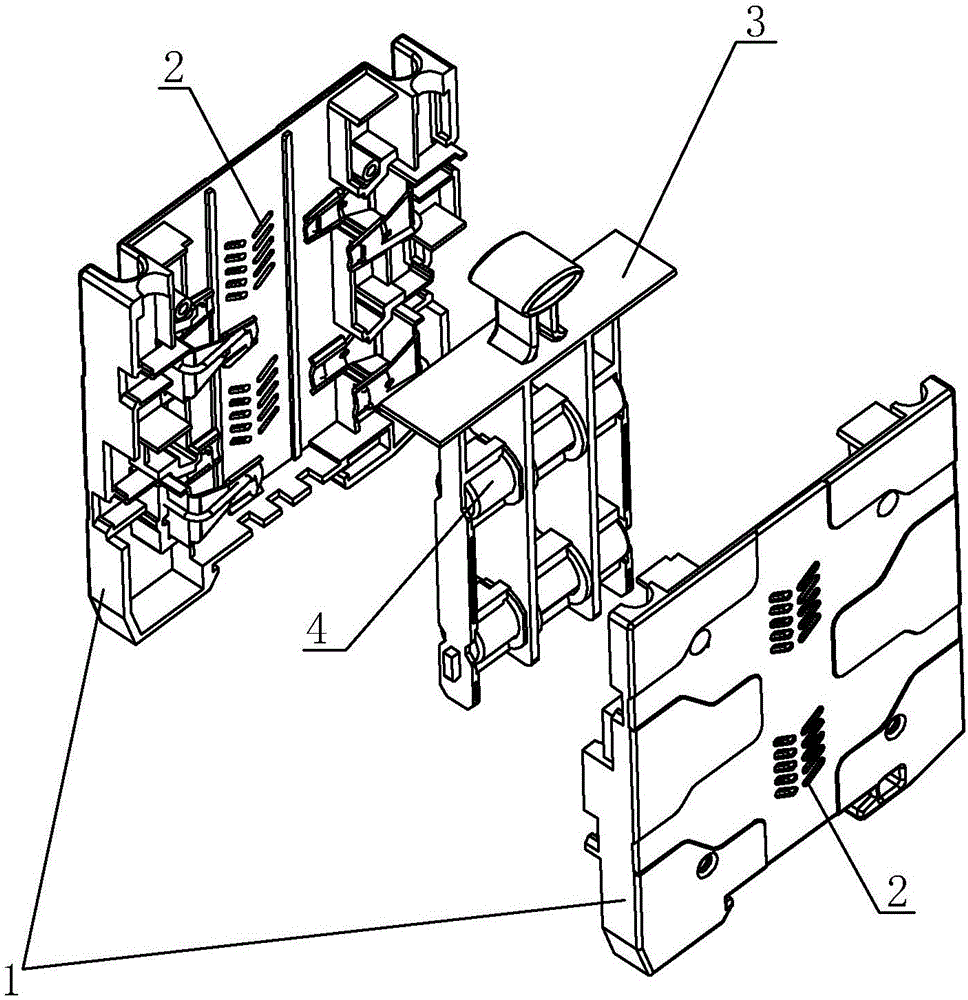
[0035] This embodiment discloses a fuse, such as figure 1 As shown, this embodiment is composed of a fuse base and a fuse body 4 installed in the fuse base. The fuse body 3 is composed of; the fuse body 4 is installed on the melt body 3; the positions corresponding to the fuse body 4 on the left housing and the right housing are provided with cooling holes 2.

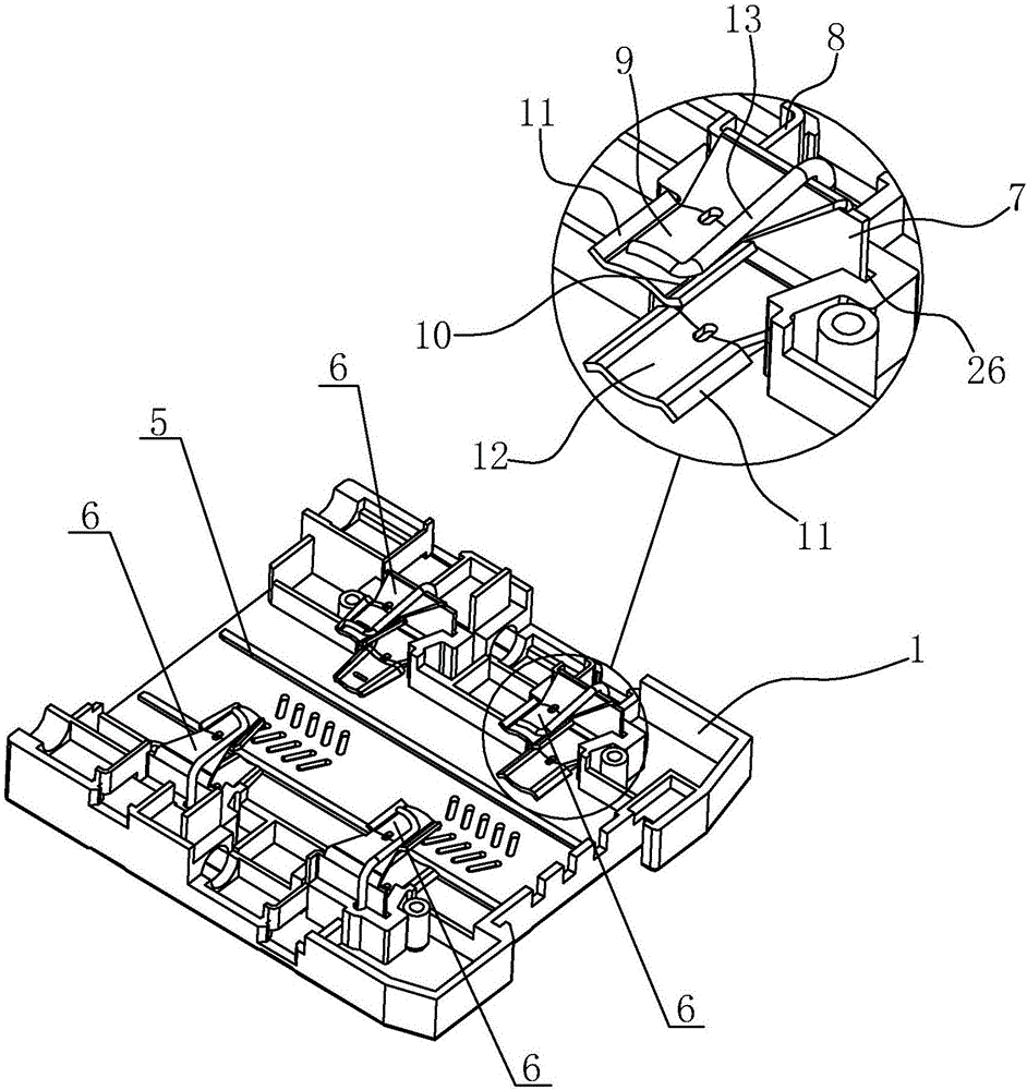
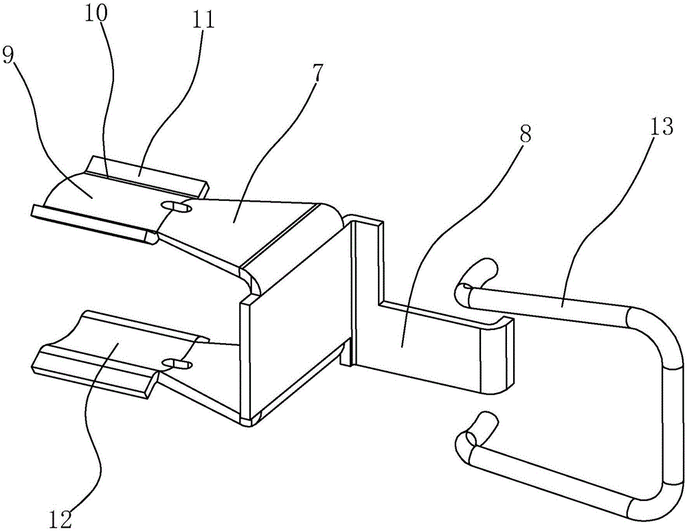
[0036] Such as figure 1 , 2 As shown, the casing 1 is provided with a chute 5 for the sliding of the melt 3 , one side of the chute 5 is distributed with two base contacts 6 along the chute 5 , and the other side of the chute 5 is also provided with two A base contact 6, the base contact 6 on both sides of the chute 5 is relatively arranged; combined figure 2 , image 3As shown, the base contact 6 includes a curved U-shaped elastic clip 7 and a terminal board 8 integrally connected with the elast...


PUM


Abstract

The invention discloses a fuse protector and fuse protector base thereof. The fuse protector base comprises a shell and a fuse puller connected with the shell in a sliding mode; at least two sets of parallel contact assemblies are arranged in the shell, and each contact assembly comprises two relative set base contacts. The base contacts comprise a spring cover-clip for clamping both ends of side wall, and electric connection parts connected with the spring cover-clip; a corresponding number of slots with the contact assemblies are arranged on the fuse pulley, and the slots comprise bayonets imbedded radically for the fuse protector and a clamping part which forms an interference fit for the fuse protector body; when the fuse puller slides out of the shell, the fuse protector body fixed in the slots and the spring cover-clip are disconnected simultaneously; when the fuse puller slides into the shell, the fuse protector body fixed in the slots and the spring cover-clip are connected simultaneously. The technology has the advantages of reducing the requirement of processing precision and improving the rate of finished products; and the technology is applied to different sizes of fuse protector body with different length, improving production efficiency and economic efficiency.

Description

technical field [0001] This invention relates to fuses, and more particularly it relates to a fuse base. Background technique [0002] The fuse base is the housing used to install the fuse. In the prior art, the Chinese patent document with the application publication number of CN105097379A discloses a fuse, and the application document discloses a fuse base structure in detail: the fuse base has at least two sets of wiring assemblies on one side, and the other There are at least two groups of wiring assemblies on one side, the wiring assemblies on both sides correspond to each other, and the fuse base is also provided with a plurality of base contacts, and each wiring assembly is connected to a base contact corresponding to its position, and the wiring assembly They are insulated from each other, and the corresponding wiring components on both sides and the corresponding base contacts are superimposed on top of each other; the carrier fuse is provided with at least two gro...

Claims


Application Information

Patent Timeline
IPC IPC(8): H01H85/20H01H85/22
CPCH01H85/20H01H85/22
Inventor 郑献昆方径林
Owner ZHEJIANG XINLI FUSE
Learn More