
Display correction method, device and system of display panel

A display panel and display brightness technology, applied to static indicators, instruments, etc., can solve problems such as time-consuming and unsuitable for batch debugging

Active Publication Date: 2017-05-31
WUHAN TIANMA MICRO ELECTRONICS CO LTD +1
View PDF10 Cites 56 Cited by
  • Summary
  • Abstract
  • Description
  • Claims
  • Application Information

AI Technical Summary

Problems solved by technology

However, the current calibration method takes a long time and is not suitable for batch debugging

Method used


Image

  • Display correction method, device and system of display panel
  • Display correction method, device and system of display panel
  • Display correction method, device and system of display panel

Examples


Embodiment Construction

[0029] The present invention will be further described in detail below in conjunction with the accompanying drawings and embodiments. It should be understood that the specific embodiments described here are only used to explain the present invention, but not to limit the present invention. In addition, it should be noted that, for the convenience of description, only some structures related to the present invention are shown in the drawings but not all structures.

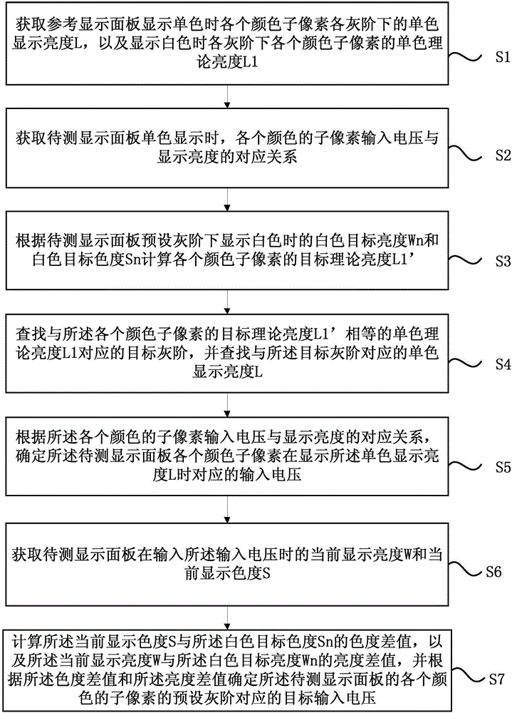
[0030] figure 1 It is a flow chart of a display correction method for a display panel provided by an embodiment of the present invention, refer to figure 1 , the method may specifically include the following steps:

[0031] S1: Obtain the monochrome display luminance L of each color sub-pixel at each gray scale when the reference display panel displays monochrome, and the monochrome theoretical luminance L1 of each color sub-pixel at each gray scale when displaying white.

[0032] Wherein, the reference display ...


PUM


Abstract

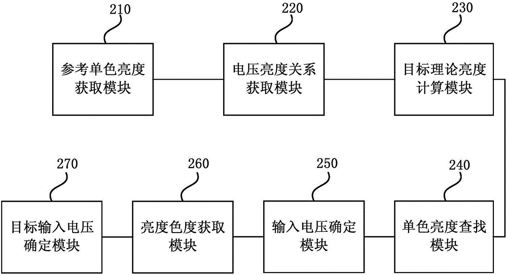
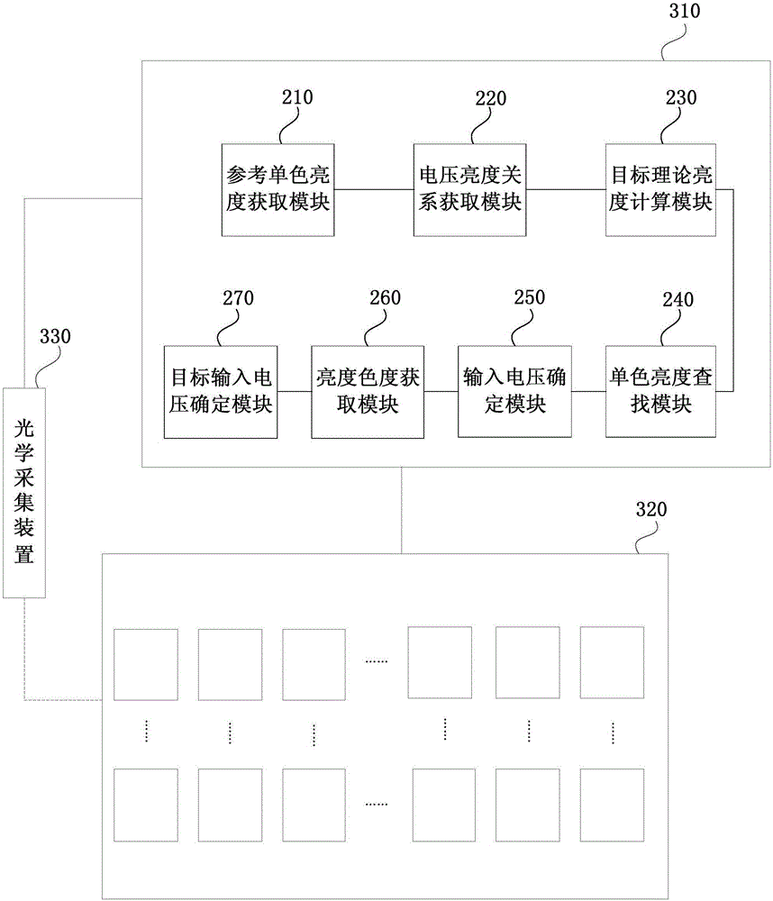
According to the embodiment, the invention discloses a display correction method, a display correction device and a display correction system of a display panel. The method comprises the following steps: acquiring monochromatic display brightness, under various gray scales, of various color sub-pixels when a reference display panel displays in monochrome, and acquiring monochromatic theoretical brightness when the reference display panel displays in white; acquiring a corresponding relation between input voltage and display brightness when a to-be-detected display panel displays in monochromatic; calculating target theoretical brightness of the various color sub-pixels in accordance with white target brightness and white target chroma when the to-be-detected display panel displays in white under a preset gray scale; searching a target gray scale corresponding to monochromatic theoretical brightness which is equal to target theoretical brightness, and searching monochromatic display brightness corresponding to the target gray scale; determining corresponding input voltages of various color sub-pixels of the to-be-detected display panel when the monochromatic display brightness is displayed; and determining target input voltage of the to-be-detected display panel in accordance with a chroma difference value and a brightness difference value. According to the embodiment, display correction method provided by the invention is short in consumed time and suitable for large-scale debugging.

Description

technical field [0001] Embodiments of the present invention relate to display technologies, and in particular to a display calibration method, device and system for a display panel. Background technique [0002] With the development of display technology, the display effect of the display panel is continuously improved, so that the application of the display panel becomes more and more extensive. [0003] The grayscale curves of display panels are different in different display fields. In addition, due to the differences in production processes and components such as driver chips, display panels cannot achieve a normal white balance state and display differences between different display panels are large. [0004] In order to meet customers' requirements for product consistency and customization, each display panel will be optically corrected during production. However, the current calibration method takes a long time and is not suitable for batch debugging. Contents of t...

Claims


Application Information

Patent Timeline
Patent Type & Authority Applications(China)
IPC IPC(8): G09G3/3208
CPCG09G3/3208G09G2320/0276G09G2320/0626G09G2320/0673
Inventor 索磊吕博嘉孔祥梓
Owner WUHAN TIANMA MICRO ELECTRONICS CO LTD
Learn More