Wireless remote control detacher control box structure

A technology of wireless remote control and control box, applied in the direction of program control and electrical program control in the sequence/logic controller, which can solve the problems of long working hours, the safety of staff cannot be guaranteed, and it is inconvenient to observe.

Inactive Publication Date: 2017-05-31
XUZHOU BO XIN MINE EQUIP MFR
View PDF0 Cites 0 Cited by
  • Summary
  • Abstract
  • Description
  • Claims
  • Application Information

AI Technical Summary

Problems solved by technology

[0002] The single-rope hoisting cage used for lifting personnel and materials in mining equipment is an essential lifting equipment. In order to ensure the safety of personnel and materials, a fall arrester is installed in the lifting cage. The fall arrester is newly installed or overhauled. , the decoupling test must be carried out, and it can be used only after passing the test; the existing decoupling device experiment is mainly the manual pulling rope type or the gas cutting method used by the mine. Production and work arrangements are greatly affected, and the operation is complicated. More importantly, safety accidents are prone to occur, and the life safety of the staff cannot be guaranteed. In order to solve the above problems, our company has studied the wireless remote control decoupler, but the wireless The control box of the remote control decoupler can only be used for one model, which has high production costs and is inconvenient for the staff to observe the working conditions of the control box.

Method used


Image

  • Wireless remote control detacher control box structure
  • Wireless remote control detacher control box structure
  • Wireless remote control detacher control box structure

Examples


Embodiment Construction

[0016] In order to make the object, technical solution and advantages of the present invention clearer, the present invention will be further described in detail below through the accompanying drawings and embodiments. However, it should be understood that the specific embodiments described here are only used to explain the present invention, and are not intended to limit the scope of the present invention.

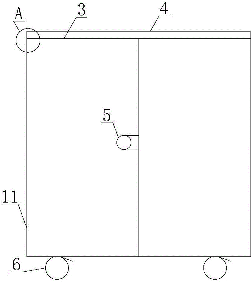
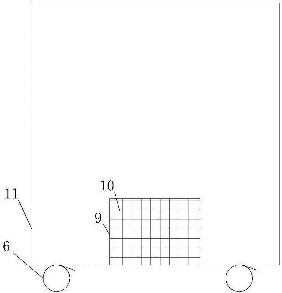
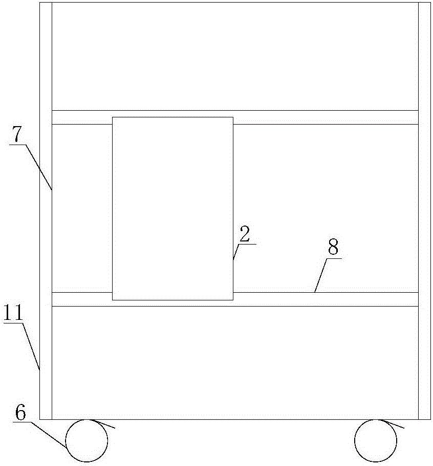
[0017] Such as Figure 1 to Figure 6 As shown, a wireless remote control decoupler control box structure, this structure is composed of a control box 1 and an electrical control system 2, the electrical control system 2 is installed inside the control box 1, and the control box 1 is controlled by a box board 3, Panel 4, lockset 5, roller 6, side plate 7, beam 8, through hole 9, mesh 10 and box body 11 are formed, and control panel 4 is installed on the upper surface of box body 11, and the front of box body 11 is connected by hinge. A box plate 3, a lock 5 is fixedly ins...


PUM


Abstract

The invention discloses a wireless remote control detacher control box structure. The wireless remote control detacher control box structure comprises a control box and an electrical control system, wherein the electrical control system is installed in the control box; the control box is composed of box boards, a control panel, a lock, rollers, side boards, a cross beam, through holes, a mesh, and a box body; the control panel is mounted on the upper surface of the box body; two box boards are connected to the front of the box body through hinges; the lock is fixedly mounted on the surface of the one box board; a power source is connected with a controller which is connected with a sensor, the sensor is connected with a wireless module, the wireless module is connected with an alarm, and the alarm is connected with a drive mechanism. The wireless remote control detacher control box structure has the advantages that more electrical devices can be loaded in the wireless remote control detacher control box structure, and the wireless remote control detacher control box structure is applicable to more types of equipment, reusable, capable of reducing production cost and capable of avoiding production resource waste.

Description

technical field [0001] The invention relates to a control box structure of a wireless remote control decoupling device, which belongs to the field of decoupling of mine tank cage anti-dropping devices. Background technique [0002] The single-rope hoisting cage used for lifting personnel and materials in mining equipment is an essential lifting equipment. In order to ensure the safety of personnel and materials, a fall arrester is installed in the lifting cage. The fall arrester is newly installed or overhauled. , the decoupling test must be carried out, and it can be used only after passing the test; the existing decoupling test is mainly the manual pull rope type or the gas cutting method used by the mine. Production and work arrangements are greatly affected, and the operation is complicated. More importantly, safety accidents are prone to occur, and the life safety of the staff cannot be guaranteed. In order to solve the above problems, our company has studied the wirele...

Claims


Application Information

Patent Timeline
IPC IPC(8): G05B19/04
CPCG05B19/04
Inventor 孙勇权明明张行理丁义梅
Owner XUZHOU BO XIN MINE EQUIP MFR
Why Eureka
Try Eureka