Embedded touch panel

A touch panel and built-in technology, applied in the fields of optics, instruments, electrical digital data processing, etc., can solve the problems of uneven box thickness, enlarged box thickness, dark lines, etc., and achieve uniform box thickness, simple manufacturing process, The effect of low production cost

Inactive Publication Date: 2017-05-31
WUHAN CHINA STAR OPTOELECTRONICS TECH CO LTD
View PDF5 Cites 11 Cited by
  • Summary
  • Abstract
  • Description
  • Claims
  • Application Information

AI Technical Summary

Problems solved by technology

Wherein, the third metal layer is usually provided with a plurality of touch electrode lines, and a flat layer (PLN) is also arranged between the second metal layer and the third metal layer, and the third metal layer is arranged on the flat layer. The existence of the metal layer, if it conflicts with the position of the columnar spacer, it is likely to cause uneven thickness of the box
[0007] like Figure 1-2 As shown, the third metal layer 160 is disposed on the flat layer 150 of the array substrate 100, and a plurality of touch electrode lines 161 are disposed in the third metal layer 160, and several columnar spacers are disposed between the color filter substrate 200 and the array substrate 100. The spacer 250 is used to control the thickness of the box. When the columnar spacer 250 is correspondingly arranged above the third metal layer 160, compared with the columnar spacer 250 not standing on the third metal layer 160, the box thickness here will be If it becomes larger, it will make the overall box thickness uneven, and it is easy to cause dark lines and other Mura
[0008] In order to avoid the uneven thickness of the box caused by the position conflict between the columnar spacer 250 and the third metal layer 160, the traditional solution is as follows: Figure 3-4 As shown, the touch electrode line 161 of the third metal layer 160 is disconnected at the position corresponding to the column spacer 250, which will cause the overall unevenness of the third metal layer 160 and poor touch performance; or, as shown in FIG. Figure 5-6 As shown, the number of touch electrode lines 161 in the third metal layer 160 is reduced, and the touch electrode lines 161 corresponding to the positions of the column spacers 250 are removed. However, this will also cause the overall unevenness of the third metal layer 160, resulting in poor display

Method used


Image

  • Embedded touch panel
  • Embedded touch panel
  • Embedded touch panel

Examples


Embodiment Construction

[0034] In order to further illustrate the technical means adopted by the present invention and its effects, the following describes in detail in conjunction with preferred embodiments of the present invention and accompanying drawings.

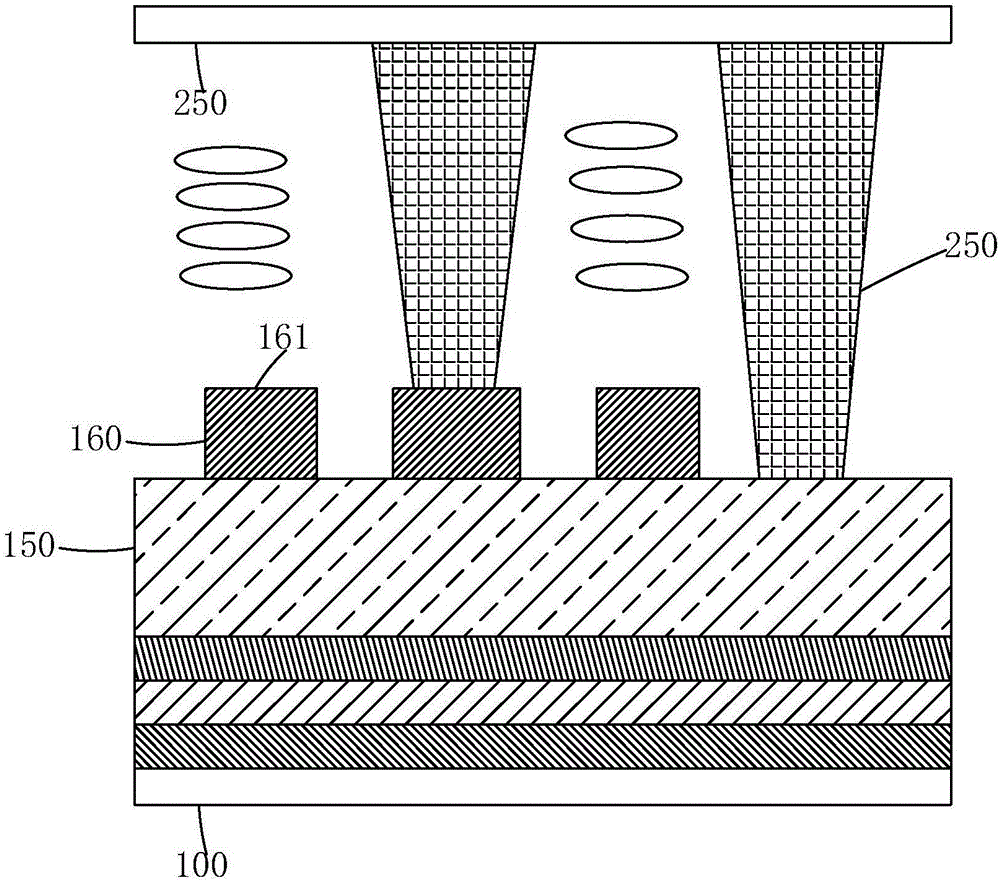
[0035] see Figure 7-8 , the present invention provides an in-cell touch panel, comprising: an array substrate 10 and a color filter substrate 20 arranged oppositely, and several columnar spacers 25 and liquid crystals arranged between the array substrate 10 and the color filter substrate 20 layer 30;

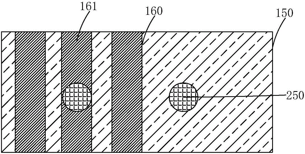
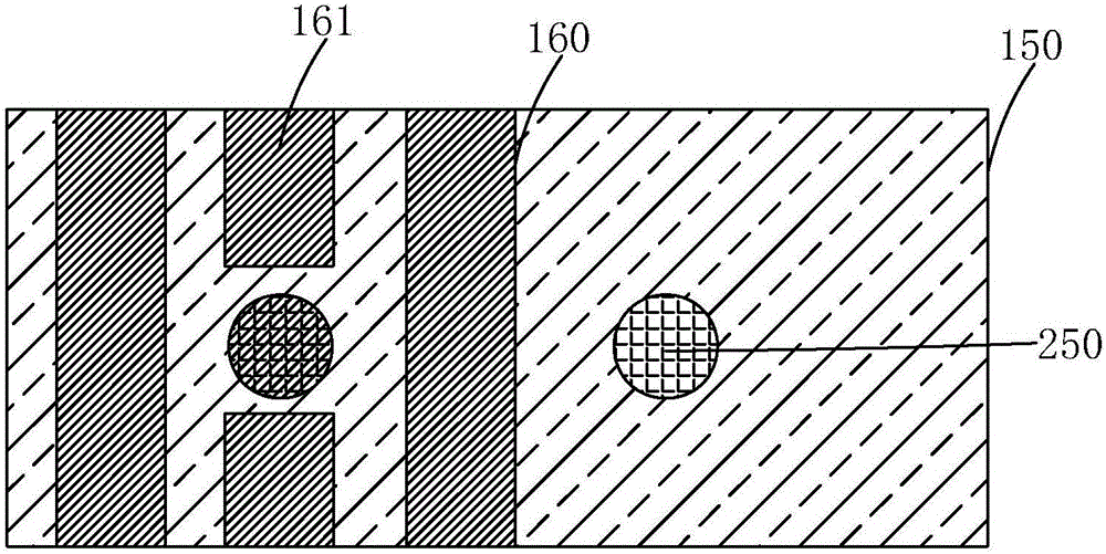
[0036] The array substrate 10 includes a first substrate 11, and a first metal layer 12, a second metal layer 13, and a third metal layer 14 that are sequentially formed on the first substrate 11 and insulated from each other; A flat layer 15 is provided between the layer 13 and the third metal layer 14, and the third metal layer 14 is formed on the upper surface of the flat layer 15;

[0037]The third metal layer 14 is provided with a plural...


PUM


Abstract

The invention provides an embedded touch panel. Multiple touch electrode lines are arranged in a third metal layer of an array substrate. The touch electrode lines on which columnar spacers stand correspondingly are overlapped touch electrode lines, grooves are formed in the regions, corresponding to the overlapped touch electrode lines, of a flat layer of the array substrate, the overlapped touch electrode lines are correspondingly arranged in the grooves, the standing height of the column spacers standing on the third metal layer correspondingly is reduced, and therefore the overall box thickness of the panel is uniform. Compared with an existing improvement method, it is not needed to disconnect the touch electrode lines in the third metal layer or reduce the number of the touch electrode lines, therefore, touch performance and pixel electric fields are not affected, only the exposure manufacturing procedure of the flat layer needs to be slightly improved on the aspect of the manufacturing procedures, the manufacturing procedures are simple, and the production cost is low.

Description

technical field [0001] The invention relates to the technical field of touch display, in particular to an embedded touch panel. Background technique [0002] With the development of display technology, liquid crystal displays (Liquid Crystal Display, LCD) and other flat display devices are widely used in mobile phones, televisions, personal Various consumer electronic products such as digital assistants, digital cameras, notebook computers, and desktop computers have become the mainstream of display devices. Most of the liquid crystal display devices currently on the market are backlight liquid crystal displays, which include a liquid crystal display panel and a backlight module. The working principle of the liquid crystal display panel is to place liquid crystal molecules between two parallel glass substrates. There are many vertical and horizontal small wires between the two glass substrates. The direction of the liquid crystal molecules is controlled by electrifying or n...

Claims


Application Information

Patent Timeline
IPC IPC(8): G02F1/1333G02F1/1362G02F1/1339G06F3/041
CPCG02F1/13338G02F1/13394G02F1/136227G06F3/041
Inventor 张春倩
Owner WUHAN CHINA STAR OPTOELECTRONICS TECH CO LTD
Why Eureka
Try Eureka