Field-eddy thermal imaging detection system and method for surface defect of steel product/billet

A detection system and thermal imaging technology, applied in the direction of material defect testing, material magnetic variables, etc., can solve the problems of uneven heating of the inspected object, inability to realize steel/billet continuous, dynamic, high-speed, accurate detection, and low detection accuracy , to achieve the effect of automatic marking, avoiding uneven heating and environmental temperature influence

Active Publication Date: 2017-05-31
UNIV OF SCI & TECH BEIJING
View PDF6 Cites 6 Cited by
  • Summary
  • Abstract
  • Description
  • Claims
  • Application Information

AI Technical Summary

Problems solved by technology

[0006] First, the existing eddy current thermal imaging detection system and method cannot realize the online, continuous, dynamic, high-speed and accurate detection of steel / billet, nor can it realize the comprehensive detection of steel / billet in all horizontal and vertical directions at the same time
[0007] Second, the existing eddy current thermal imaging detection systems and methods only target a single target individual detection, which cannot satisfy a set of systems and methods to detect products of different materials, shapes and sizes
In the actual inspection process, it is easy to cause uneven heating of the inspected object, resulting in poor imaging effect and low defect detection accuracy
[0009] Fourth, the existing eddy current thermal imaging inspection systems and methods are only aimed at identifying the defects of the inspected object, and fail to realize accurate and automatic marking of defects

Method used


Image

  • Field-eddy thermal imaging detection system and method for surface defect of steel product/billet
  • Field-eddy thermal imaging detection system and method for surface defect of steel product/billet
  • Field-eddy thermal imaging detection system and method for surface defect of steel product/billet

Examples


Embodiment 1

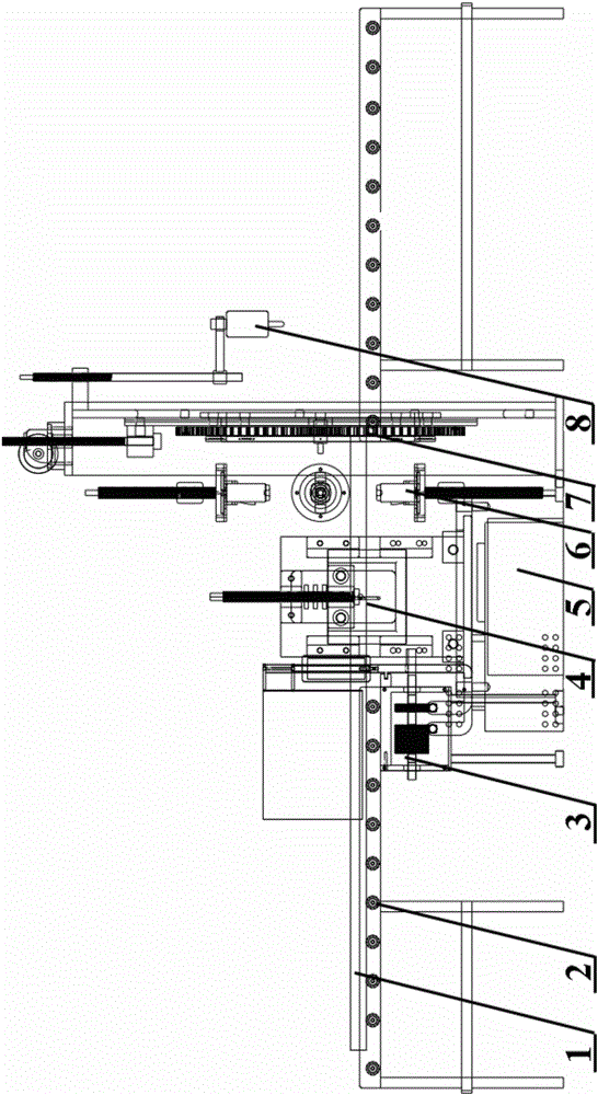
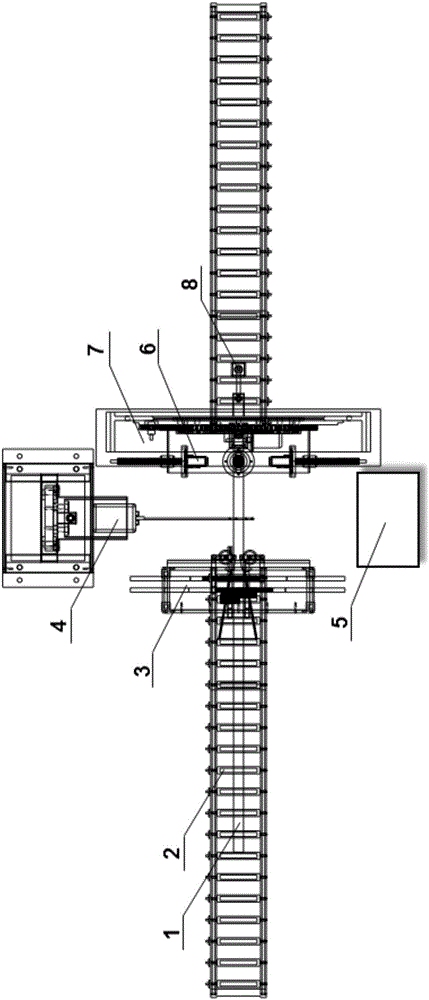
[0069] Select the Q345 rectangular pipe for construction as the object to be inspected, and its cross-section is 125mm×125mm. First adjust the distance between the left wheel 31a and the right wheel 31b between 125mm-125.2mm; then adjust the distance from the lens of the infrared thermal imager 6 to the surface of the square tube to be 600mm; then adjust the position of the high-frequency induction heating device 4, select as Figure 5 The induction heating coil shown ensures that the center of the cross-section of the rectangular tube coincides with the center of the coil, the coil lift is between 5mm-10mm, and the lateral distance between the coil and the lens of the infrared thermal imaging camera 6 is within 5cm. At the same time, turn on the switch of the feeding frame, high-frequency induction heating equipment and infrared thermal imager, set the conveying speed of the feeding frame to 6m / min, and heat the surface temperature of the square tube to 160°C-180°C instantane...


PUM


Abstract

The invention relates to a field-eddy thermal imaging detection system and a method for a surface defect of a steel product / billet. The system can be embedded into a steel product / billet forming production line as an automatic detection and marking module. The method comprises the following steps that a) a to-be-detected object enters an aligning device by a feeding rack; b) the surface temperature of the steel product / billet is transiently heated by high-frequency induction heating equipment in a heating area; c) a thermal infrared imager detection area is entered; d) a thermal infrared imager transmits a signal to a PC (Personal Computer) to obtain temperature difference data of an image and aftertreatment is performed on the image; and e) when the temperature difference of the image is greater than or less than a certain designated value, the PC gives an alarm and transmits a signal to an automatic spray gun for marking to realize automatic marking of a defect position. The method is high in detection speed and high in efficiency, avoids influences caused by nonuniform heating and environmental factors, and can accurately identify and mark the surface defect of the steel product / billet.

Description

technical field [0001] The invention relates to the fields of non-destructive testing, product quality control and the like, in particular to an eddy current thermal imaging detection system and method for steel / billet surface defect fields. Background technique [0002] Since the economic crisis, the iron and steel industry has faced enormous challenges, and many iron and steel enterprises have faced losses. In the cold winter of the iron and steel industry, facing various dilemmas such as declining profits, overcapacity, and vicious competition in the industry, seeking enterprise transformation, researching and developing high-tech products, and shifting from the extensive type of winning by quantity to the high-tech winning by quality has become the only way out . [0003] In the past 20 years, some iron and steel enterprises and equipment suppliers at home and abroad have been actively engaged in the research of steel / billet surface quality on-line inspection technology...

Claims


Application Information

Patent Timeline
Patent Type & Authority Applications(China)
IPC IPC(8): G01N27/90G01N25/72
CPCG01N25/72G01N27/90
Inventor 韩静涛苏伯泰张永军
Owner UNIV OF SCI & TECH BEIJING
Why Eureka
Try Eureka