Water application pipeline laying facility

A technology of pipeline laying and water laying method, which is applied in the direction of pipeline laying and maintenance, pipes, machinery and equipment, etc. It can solve the problems of high requirements for laying equipment, slow laying speed, and insufficient laying, so as to protect the external corrosion of pipelines and reduce the requirements. and operation complexity, the effect of improving the laying speed

Inactive Publication Date: 2017-05-31
BEIJING MUNICIPAL BRIDGE MAINTENANCE MANAGEMENT +1
View PDF6 Cites 3 Cited by
  • Summary
  • Abstract
  • Description
  • Claims
  • Application Information

AI Technical Summary

Problems solved by technology

[0012] The purpose of the present invention is to provide a pipeline laying facility by water laying method, which can solve the problems existing in the prior art, such as high requirements for laying equipment, cumbersome operation, poor safety, slow laying speed, damaged structure and inadequate laying.

Method used


Image

  • Water application pipeline laying facility
  • Water application pipeline laying facility
  • Water application pipeline laying facility

Examples


Embodiment Construction

[0033] In order to be able to understand the above objectives, features and advantages of the present invention more clearly, the present invention will be further described in detail below in conjunction with the accompanying drawings and specific embodiments. It should be noted that the embodiments of the application and the features in the embodiments can be combined with each other if there is no conflict.

[0034] In the description of the present invention, it should be noted that the terms "center", "vertical", "horizontal", "upper", "lower", "front", "rear", "left", "right", " The orientation or positional relationship indicated by "vertical", "horizontal", "top", "bottom", "inner", "outer" etc. is based on the orientation or positional relationship shown in the drawings, and is only for the convenience of describing the present invention and The description is simplified, rather than indicating or implying that the pointed device or element must have a specific orientati...


PUM


Abstract

The invention relates to the technical field of pipeline laying and provides water application pipeline laying facility which comprises a first water retaining wall mounted at an entrance port of a sleeve, wherein a pipeline-through hole for penetrating into a pipeline is formed in the first water retaining wall. When the water application pipeline laying facility is applied to pipeline laying, after the end part of the to-be-laid pipeline penetrates into the pipeline-through hole in the first water retaining wall, liquid can be injected into a liquid accommodating chamber. At the moment, the pipeline entering the sleeve undergoes vertical upward buoyancy, then the acting force for a pipeline laying process is reduced, the requirements on the laying equipment as well as the operation complexity are lowered, the construction safety and laying speed are improved, and the pipeline is laid in place for sure. Moreover, since a support member is mounted in advance and then drives the pipeline to enter the sleeve, the damage and deformation of the support member can be prevented; meanwhile, the frictional resistance against the pipeline is reduced under the buoyancy, and thus the pipeline is effectively protected from outer corrosion.

Description

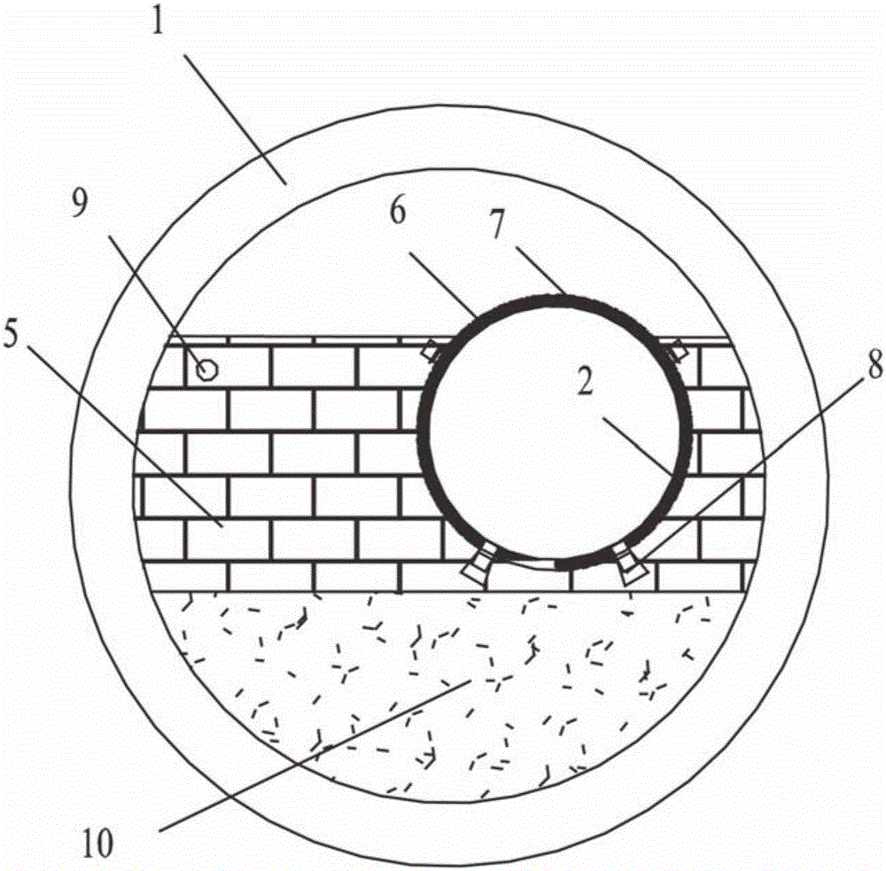
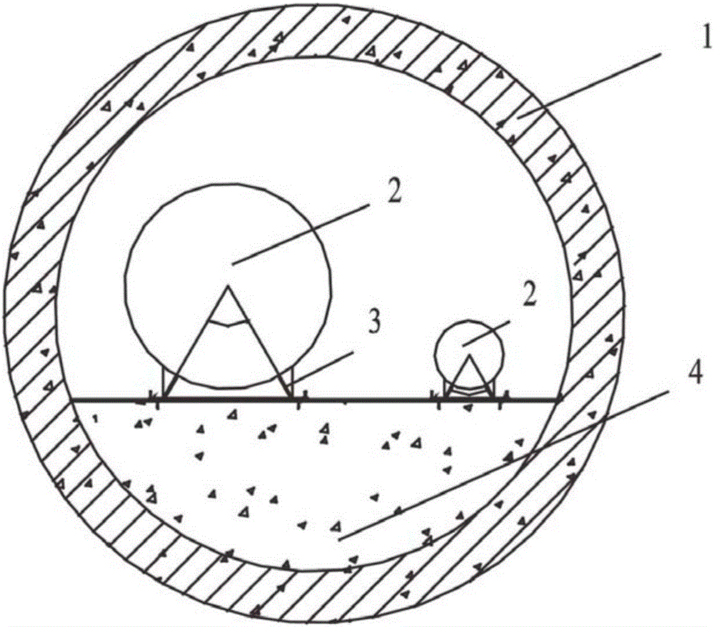
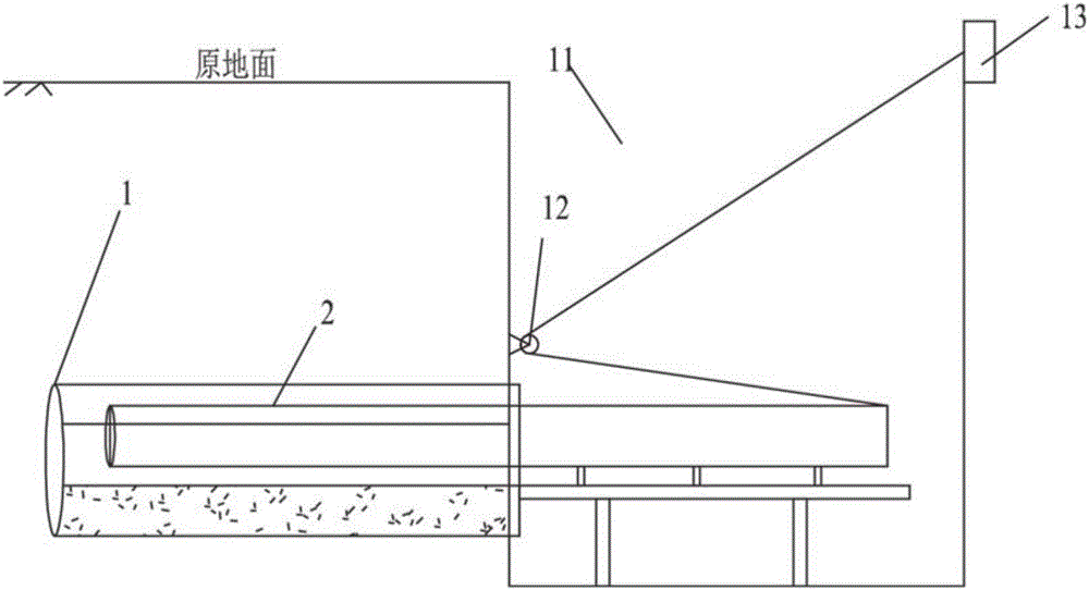
Technical field [0001] The invention relates to the technical field of pipeline laying, and provides a water laying method pipeline laying facility. Background technique [0002] In the construction of the municipal supporting pipeline project on Cuihu East Road (North Side Road of Jingmi Water Diversion Canal-Cuihu South Road) in Haidian District-the reclaimed water project, the reclaimed water pipeline passes through Beiqing Road, the landscape river is planned and the Dazhai Canal section is planned. Among them, the reclaimed water pipelines corresponding to Beiqing Road, the planned landscape river and the planned Dazhai canal section are 133.5m, 97.5m and 65.5m long respectively. Since the construction site does not have the open slot condition, the prior art proposes to install the casing in place by the jacking method first, and then lay the reclaimed water pipeline in the casing. [0003] See figure 1 , The casing adopts a reinforced concrete casing with a diameter of 3000...

Claims


Application Information

Patent Timeline
Patent Type & Authority Applications(China)
IPC IPC(8): F16L1/028F16L5/02
CPCF16L1/028F16L5/02
Inventor 牛存良翟佳李明许博刘永杨磊冯建勇苏斌
Owner BEIJING MUNICIPAL BRIDGE MAINTENANCE MANAGEMENT
Why Eureka
Try Eureka