
Method and device for pressure detection and control

A pressure and pressure value technology, applied in the field of pressure monitoring, can solve the problems of pressure value fluctuation, failure to discover the hydraulic system in time, and failure to monitor the pressure value of the hydraulic system of the clamping machine.

Inactive Publication Date: 2017-05-31
GREE ELECTRIC APPLIANCES INC
View PDF10 Cites 0 Cited by
  • Summary
  • Abstract
  • Description
  • Claims
  • Application Information

AI Technical Summary

Problems solved by technology

[0005] The present invention provides a method and device for pressure monitoring, which is used to solve the problem in the prior art that the pressure value applied by the hydraulic system of the clamping machine cannot be monitored in real time, so that the fluctuation of the pressure value applied by the hydraulic system cannot be found in time The problem

Method used


Image

  • Method and device for pressure detection and control
  • Method and device for pressure detection and control
  • Method and device for pressure detection and control

Examples


Embodiment Construction

[0033] In order to make the purpose, technical solutions and advantages of the present invention clearer, the present invention will be further described in detail below in conjunction with the accompanying drawings. Obviously, the described embodiments are only some of the embodiments of the present invention, rather than all of them. Based on the embodiments of the present invention, all other embodiments obtained by persons of ordinary skill in the art without making creative efforts belong to the protection scope of the present invention.

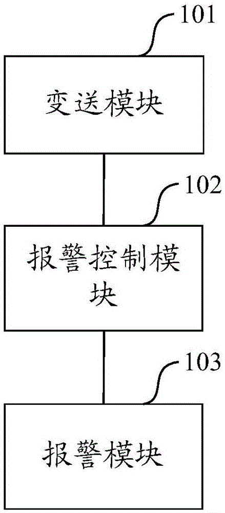
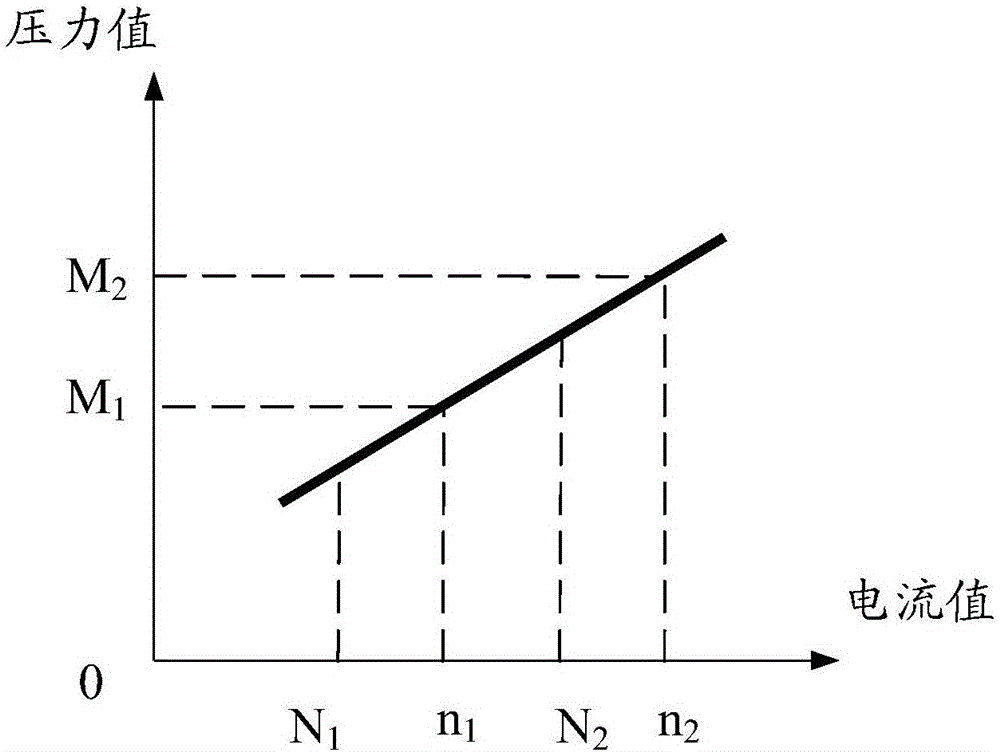
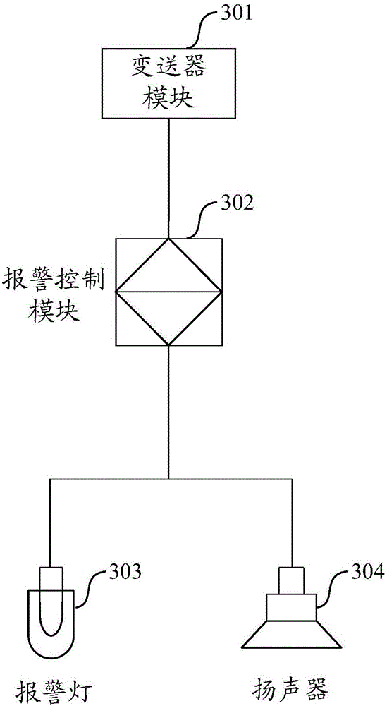
[0034] Such as figure 1 As shown, a device for pressure monitoring provided by the embodiment of the present invention is connected to the hydraulic system of the clamping machine, and the device includes: a transmission module 101 for outputting a current value according to the pressure value of the hydraulic system, and an alarm control module 102 And an alarm module 103 ; wherein, the current output terminal of the transmission modul...


PUM


Abstract

The invention relates to the field of mechanical control, in particular to a method and device for pressure detection and control. The device is connected with a hydraulic system of a clamping and holding machine. The device comprises a transmitting module used for outputting current value according to pressure value of the hydraulic system, an alarm control module and an alarm module. A current output end of the transmitting module is connected with one end of the alarm control module. The other end of the alarm control module is connected with the alarm module. Due to the fact that the device is utilized for monitoring pressure value of the hydraulic system, pressure value of the hydraulic system of the clamping and holding machine can be monitored in a real-time manner so that pressure fluctuations of the hydraulic system can be timely found out.

Description

technical field [0001] The invention relates to the field of mechanical control, in particular to a method and device for pressure monitoring. Background technique [0002] At present, the clamping method is generally used in the handling and turnover of electrical appliances or other goods, that is, the clamping machine is used to clamp the goods to make the goods off the ground and carry them. During the operation of the clamping machine, the hydraulic system, such as a hydraulic pump, exerts pressure on the clamping arm, so that the clamping arm tightens the goods, so that the goods can be lifted off the ground with the lifting of the clamping arm, and pass through the clamping machine for horizontal movement. [0003] During the use of the clamping machine, in order to prevent the goods from falling off due to the small pressure applied by the hydraulic system and to prevent the goods from being damaged due to the high pressure applied by the hydraulic system, it is nec...

Claims


Application Information

Patent Timeline
Patent Type & Authority Applications(China)
IPC IPC(8): F15B19/00
CPCF15B19/00
Inventor 黄汉兴陆郁
Owner GREE ELECTRIC APPLIANCES INC
Learn More