Frame structure
A frame structure and unified technology, applied in the direction of building structure, construction, etc., can solve the problems that the main components cannot be manufactured in a factory standardization, and the ductility of the beamless slab is poor, so as to achieve easy processing and installation, strong stability, and uniform force Effect
- Summary
- Abstract
- Description
- Claims
- Application Information
AI Technical Summary
Problems solved by technology
Method used
Image
Examples
Embodiment 1
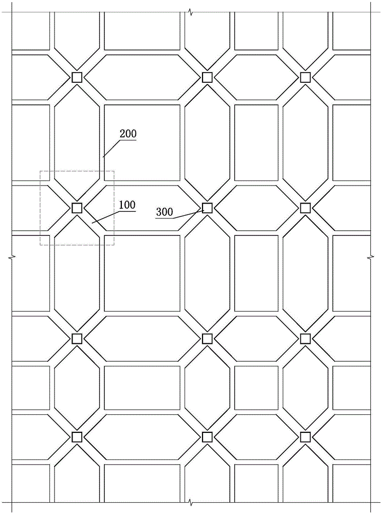
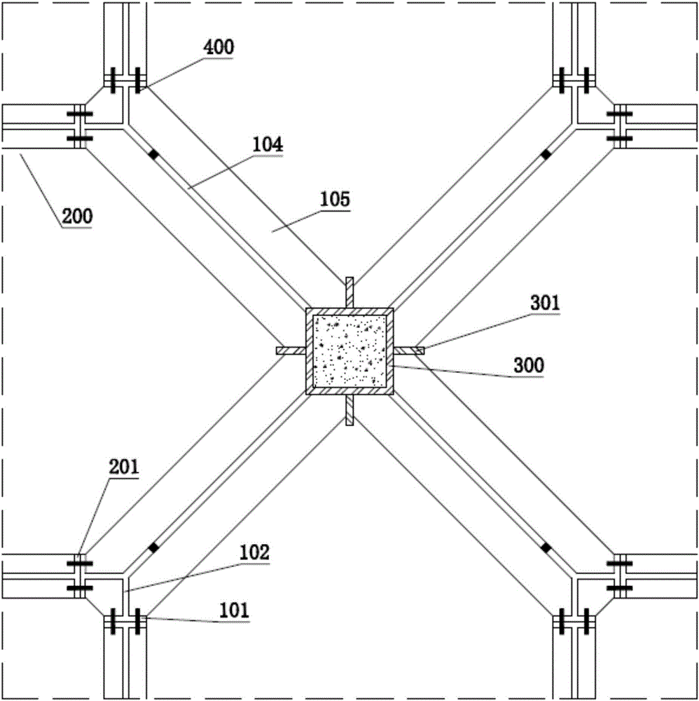
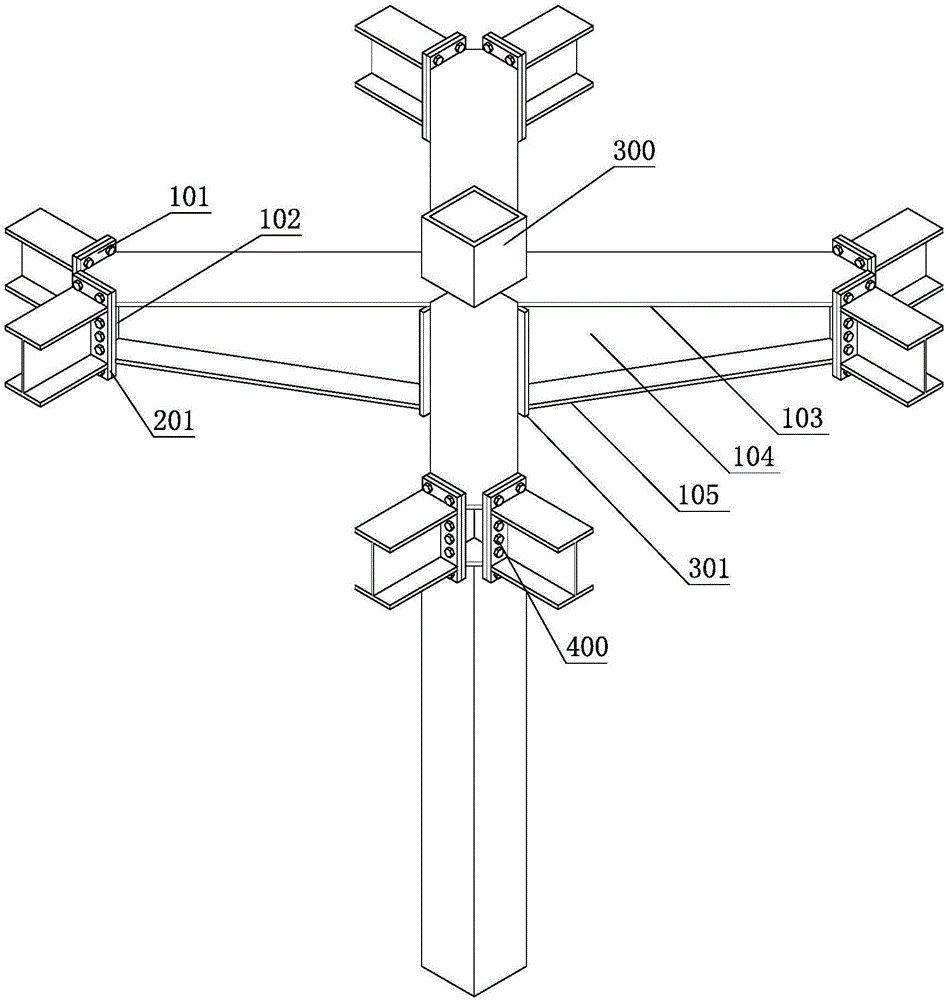
[0044] figure 1 It is a top view of the frame structure of Embodiment 1 of the present invention; figure 2 is the invention figure 1 A partial schematic diagram of the connection between the cross beam and beam B; image 3 yes figure 2 The perspective view of the part shown is connected to the support column at the upper part; Figure 4 yes figure 2 The part shown is a perspective view of the upper unattached support column.
[0045] In the figure, the meanings indicated by each reference sign are as follows; 100, beam armor; 101, connecting vertical plate armor; 102, supporting vertical plate armor; 103, upper flange plate armor; 104, web plate armor; 105, lower flange Plate A; 200, beam B; 201, connecting vertical plate B; 300, supporting column; 301, reinforcing rib; 302, pouring hole; 400, bolt.
[0046] A frame structure, comprising a cross beam, the middle part of which is used to connect with the support column 300, the cross beam includes a plurality of beam a...
Embodiment 2
[0059] Figure 5 It is a partial schematic diagram of the connection between the cross beam and beam B in Embodiment 2 of the present invention; Figure 6 yes Figure 5 The perspective view of the part shown is connected to the support column at the upper part; Figure 7 yes Figure 5 The part shown is a perspective view of the upper unattached support column. In the figure, the same reference numerals as those used in the above-mentioned embodiments still follow the definition of the reference numerals in the above-mentioned embodiments. The meanings represented by the newly appearing reference signs in the figure are as follows: 106, connecting the vertical plate C; 202, connecting the vertical plate D; 203, the upper flange plate B; 204, the web plate B; 205, the lower flange plate B.
[0060] The difference between this embodiment and embodiment 1 is:
[0061] Beam A 100 and Beam B 200 are H-shaped steel. Beam A 100 has upper flange A 103, web A 104 and lower flange A...
Embodiment 3
[0064] Figure 8 It is a partial schematic diagram of the connection between the cross beam and beam B in Embodiment 3 of the present invention; Figure 9 yes Figure 8 The shown partial perspective view of connecting support columns at the upper part can be used for middle floors other than the top floor; Figure 10 yes Figure 8 The perspective view shown partially in the upper part without supporting columns can be used for the top floor. In the figure, the same reference numerals as those used in the above-mentioned embodiments still follow the definition of the reference numerals in the above-mentioned embodiments. The meanings of the newly appearing reference signs in the figure are as follows: 601, beam longitudinal reinforcement; 602, beam stirrup;
[0065] The difference between this embodiment and embodiment 1 is:
[0066] The frame structure is a reinforced concrete structure, beam A 100 and beam B 200 share beam longitudinal reinforcement 601; Figure 10 The ...
PUM
 Abstract
Description
Claims
Application Information
 - Generate Ideas
- Intellectual Property
- Life Sciences
- Materials
- Tech Scout
- Unparalleled Data Quality
- Higher Quality Content
- 60% Fewer Hallucinations
Browse by: Latest US Patents, China's latest patents, Technical Efficacy Thesaurus, Application Domain, Technology Topic, Popular Technical Reports.
© 2025 PatSnap. All rights reserved.Legal|Privacy policy|Modern Slavery Act Transparency Statement|Sitemap|About US| Contact US: help@patsnap.com


