Eureka AIR delivers breakthrough ideas for toughest innovation challenges, trusted by R&D personnel around the world.

A pressure dispersing anchor cable and its installation method

A decentralized, anchor cable technology, which is applied in construction, foundation structure engineering, sheet pile walls, etc., can solve the problems of cumbersome installation of limit pieces, and achieve the effects of improving cable manufacturing efficiency, convenient installation, and reliable structure

Active Publication Date: 2019-11-01
LIUZHOU OVM MASCH CO LTD +1
View PDF6 Cites 0 Cited by
  • Summary
  • Abstract
  • Description
  • Claims
  • Application Information

AI Technical Summary

Problems solved by technology

[0003] The purpose of the present invention is to provide a pressure-dispersing anchor cable and its installation method to solve the cumbersome problems existing in the installation of large-hole pressure-dispersing anchor cables and spacers in the prior art, so as to improve the pressure of large holes Cable-making Efficiency of Decentralized Anchor Cable

Method used


Image

  • A pressure dispersing anchor cable and its installation method
  • A pressure dispersing anchor cable and its installation method
  • A pressure dispersing anchor cable and its installation method

Examples


Embodiment 1

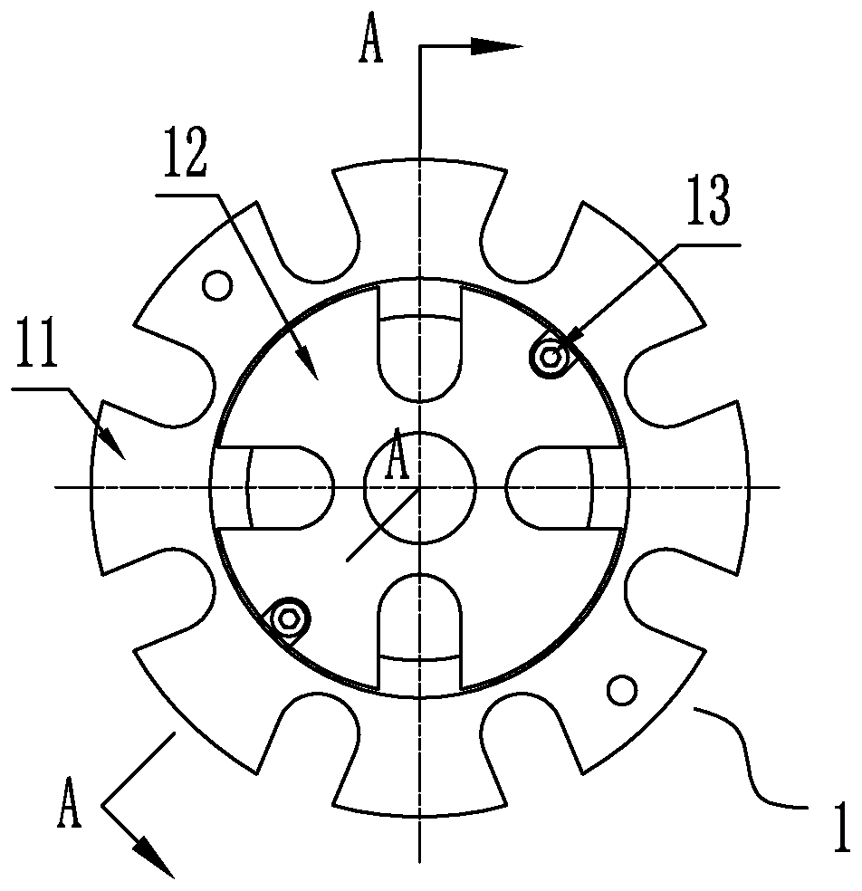
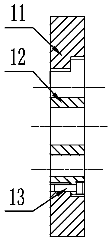
[0088] A combined bearing plate for a pressure-distributed anchor cable, such as Figure 1-Figure 2 As shown, the combined bearing plate includes an outer bearing plate 11 and an inner bearing plate 12;

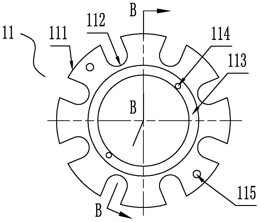
[0089] Such as Figure 3-Figure 4 As shown, the outer bearing plate 11 includes an annular outer bearing plate body 111, the outer edge of the outer bearing plate body 111 is provided with 8 arc-shaped grooves I112 for installing prestressed tendons, and the upper surface of the outer bearing plate body 111 is A bolt hole 115 is opened, and the center of the outer bearing plate body 111 is an annular step hole I113, and a screw hole 114 is opened on the annular step hole I113;

[0090] Such as Figure 5-Figure 7 As shown, the inner bearing plate 12 includes a circular inner bearing plate body 121; the outer edge of the inner bearing plate body 121 is an annular step I123, on which are provided four arc-shaped grooves II122 for installing prestressed tendons, There is a scr...

Embodiment 2

[0095] A pressure-dispersing anchor cable such as Figure 9 As shown, the pressure-dispersing anchor cable includes an outer anchor head part and an inner anchor section, and the inner anchor section includes an anchor cable body and a multi-stage cable body bearing structure, and the first-stage bearing structure of the cable body is formed by an extruded anchor The permanent load-bearing structure composed of bearing plate I and other load-bearing structures at all levels is a permanent load-bearing structure composed of extruded anchors and bearing plate II or extruded anchors and bearing plate III. The extruded anchors are composed of The extruded anchor formed on the prestressed tendon by extruding the sleeve and the anchoring medium to extrude and anchor;

[0096] The bearing plate I of the first-level bearing structure may be the existing bearing plate 8, or the inner bearing plate 12 of the combined bearing plate 1 described in Embodiment 1 of the present invention;

...

Embodiment 3

[0110]A method for installing a pressure-dispersing anchor cable.

[0111] It is the installation method of the pressure dispersion type anchor cable and anchor cable described in embodiment two, and its specific steps are:

[0112] A. Install the first level bearing structure:

[0113] A1, install the carrier 3 on the prestressed tendons;

[0114] A2. Install the prestressed tendon with the carrier 3 on the bearing plate I, the bearing plate I is the existing bearing plate 8

[0115] A3. Install the ordinary limit plate 9;

[0116] A4. Use the bolt 6 and the nut 7 to position the existing bearing plate 8 and the common limiting plate 9 on the extrusion sleeve;

[0117] B. Install the second level bearing structure:

[0118] B1, install the bearing body 3 on the prestressed tendons;

[0119] B2. Install prestressed tendons with a carrier 3 on the bearing plate II, the bearing plate II is a combined bearing plate II1b:

[0120] B21. Install prestressed tendons on the inne...


PUM


Abstract

The invention discloses a pressure-dispersion type anchor cable. An inner anchoring section of the pressure-dispersion type anchor cable comprises an anchor cable body and a multi-stage cable body bearing structure. Apart from a first stage bearing plate, other stages of bearing plates are combined-type bearing plates. Limiting plates are also combined-type limiting plates. Each combined-type bearing plate comprises an outer bearing plate and an inner bearing plate. Arc grooves I used for mounting prestressed tendons are formed in the periphery of a circular ring shaped outer bearing plate body of each outer bearing plate. Arc grooves II used for mounting the prestressed tendons are formed in the periphery of a circular ring shaped inner bearing plate body of each inner bearing plate. Injection pipe mounting holes are formed in the centers of the inner bearing plate bodies and inner limiting plates. In a using state, annular step holes I of the inner bearing plates / inner limiting plates are matched with annular step holes I of the outer bearing plates / outer limiting plates, and the annular step holes I of the inner bearing plates / inner limiting plates and the annular step holes I of the outer bearing plates / outer limiting plates are connected to be a whole through screws to combine the combined-type bearing plates / the combined-type limiting plates. According to the anchor cable, the problem that mounting of large hole site pressure-dispersion type anchor cable bearing plates and limiting pieces is complex is solved, the mounting difficulty of the prestressed tendons of inner rings of the anchor cable bearing plates is reduced, and the cable manufacturing efficiency is improved.

Description

technical field [0001] The invention relates to an anchor cable and an installation method thereof, in particular to an anchor cable of a large hole position pressure dispersion type and a production and installation method thereof. Background technique [0002] The pressure-distributed anchor cable has the characteristics of more uniform compressive stress distribution in the inner anchorage section, high single-hole bearing capacity, and more reliable anchor cable anchorage, and has been widely used in geotechnical engineering. At present, the structure of the bearing plate and the limit plate used for the pressure dispersion type anchor cable are as described in the patent No. 201320512838.X "tension and compression dispersion type anchor cable bearing plate". For the second-level and third-level load-bearing structures of the pressure-distributed anchor cable, it is time-consuming and cumbersome to install the prestressed tendons of the inner ring with the existing load-...

Claims


Application Information

Patent Timeline
Patent Type & Authority Patents(China)
IPC IPC(8): E02D5/74
CPCE02D5/74E02D2250/0046
Inventor 庞锐剑雷欢曹佼覃磊韦耀淋
Owner LIUZHOU OVM MASCH CO LTD
Why Eureka
Eureka Blog
Learn More