Target rod removing device

A target stick and baseball technology, applied in the field of auxiliary facilities, can solve the problems of unbalanced force application, damage to the target stick, the quality of the optical fiber preform and the influence of the utilization rate, etc., to achieve the effect of ensuring balance and avoiding pollution

Active Publication Date: 2017-05-31
QINGHAI ZHONGLI OPTICAL FIBER TECH CO LTD
View PDF18 Cites 1 Cited by
  • Summary
  • Abstract
  • Description
  • Claims
  • Application Information

AI Technical Summary

Problems solved by technology

[0003]The target rod needs to be removed before the optical fiber preform enters the next process such as the wire drawing process. In the existing technology, online workers generally remove the target rod manually. There are the following deficiencies: First, due to the unbalanced force applied during the manual removal process, the probability of damaging the hole in the center hole of the optical fiber preform is relatively high, which has a certain impact on the quality and utilization of the optical fiber preform; Second, the labor intensity of online operators is high; third, there is a risk of damage to the target rod, which affects the turnover and use of the target rod; fourth, the surface of the optical fiber preform is polluted (caused by touching during the removal process)
[0004] The applicant has carried out literature search, but in the Chinese and foreign patents and non-patent literature disclosed so far, it is not found that the target rod is replaced by a machine from an optical fiber preform The technical information about pulling out, the technical solution to be introduced below is generated under this background

Method used


Image

  • Target rod removing device
  • Target rod removing device

Examples


Embodiment Construction

[0019] In order to understand the technical essence and beneficial effects of the present invention more clearly, the applicant will describe in detail the following examples, but the descriptions of the examples are not intended to limit the solutions of the present invention. Equivalent transformations that are only formal but not substantive should be regarded as the scope of the technical solution of the present invention.

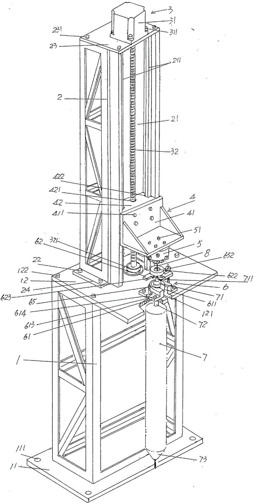
[0020] In the following descriptions, all directional or azimuth concepts such as up, down, left, right, front, back, top and bottom are aimed at figure 1 As far as the current position is concerned, it cannot be understood as a special limitation on the technical solution provided by the present invention.

[0021] See figure 1 , showing a hollowed-out frame-shaped base 1; showing a hollow-out frame-shaped lifting slide support frame 2, which is fixed to the top of the aforementioned base 1; showing A lifting slide drive mechanism 3, the lifting sli...


PUM


Abstract

The invention provides a target rod removing device and belongs to the technical field of supporting facilities in optical fiber production. The target rod removing device comprises a base, a lifting slide table supporting frame, a lifting slide table driving mechanism, a lifting slide table, a target rod clamping jaw disc and an optical fiber preform suspending and locking mechanism, wherein the lifting slide table supporting frame is fixed with the top of the base; the lifting slide table driving mechanism is arranged on the lifting slide table supporting frame; the lifting slide table is in slide fit with the lifting slide table supporting frame and in driving fit with the lifting slide table driving mechanism; the target rod clamping jaw disc is fixed on the lifting slide table; the optical fiber preform suspending and locking mechanism is arranged at the top of the base and correspondingly below the target rod clamping jaw disc. The target rod removing device has the advantages that balance of applied force can be guaranteed in the target rod removing process; the operating intensity is reduced, and the efficiency is high; a central hole of an optical fiber preform and the target rod cannot be damaged, and pollution to the surface of the optical fiber preform can be avoided.

Description

technical field [0001] The invention belongs to the technical field of auxiliary facilities in optical fiber production, and in particular relates to a target rod removal device. Background technique [0002] Since the functions of the aforementioned target rods are well known and can also be referred to the Chinese Invention Patent Authorization Announcement No. CN1286751C, etc., the applicant will not repeat them. As known in the industry, currently optical fiber preforms are mainly prepared by chemical vapor deposition, such as external vapor deposition (OVD), modified chemical vapor deposition (MCVD), plasma chemical vapor deposition (PCVD) method) and axial vapor deposition method (VAD method). This application is aimed at target rods used in the production of optical fiber preforms by the external vapor deposition method (OVD method). The material of the target rod is silicon dioxide or aluminum trichloride and so on. The target rod mentioned in the aforementioned C...

Claims


Application Information

Patent Timeline
Patent Type & Authority Applications(China)
IPC IPC(8): C03B37/018
CPCC03B37/018
Inventor 卫晓明刘世浩徐作臣蒲冬林窦生效马晓光杨洋张兴飞谢康
Owner QINGHAI ZHONGLI OPTICAL FIBER TECH CO LTD
Why Eureka
Try Eureka