
Controllable vacuumizing pipeline device for forming mold for transparent part of aircraft

A technology for forming molds and vacuum tubes, which is applied in the field of controllable vacuum pipeline devices for forming molds for transparent parts of aircraft, and can solve problems such as uncontrollable vacuum degree, easy wrinkles in glass forming, and cloth lines on the surface

Inactive Publication Date: 2017-05-31
JIANGXI HONGDU AVIATION IND GRP
View PDF3 Cites 0 Cited by
  • Summary
  • Abstract
  • Description
  • Claims
  • Application Information

AI Technical Summary

Problems solved by technology

The traditional pipeline cannot control the vacuum degree, so that when forming large, thin, and large-curvature transparent parts, the transparent part is easy to be over-molded with the mold, and the surface will produce texture. Forming is prone to wrinkles

Method used


Image

  • Controllable vacuumizing pipeline device for forming mold for transparent part of aircraft
  • Controllable vacuumizing pipeline device for forming mold for transparent part of aircraft
  • Controllable vacuumizing pipeline device for forming mold for transparent part of aircraft

Examples


Embodiment Construction

[0024] The present invention is described in detail below in conjunction with accompanying drawing:

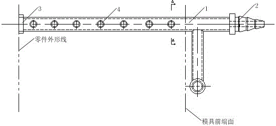
[0025] A controllable vacuum pumping pipeline device for a forming mold of an aircraft transparent part, which includes a vacuum pipeline and a vacuum pumping device;

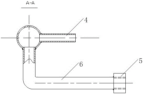
[0026] The exhaust pipe 1, branch pipe 4 and elbow 6 on the vacuum pipeline are integrated by welding, the elbow 6 is welded on the front end of the exhaust pipe 1, and the other end of the elbow 6 is welded with a vacuum pressure gauge connector 5;

[0027] A plurality of branch pipes 4 are welded in the radial direction of the exhaust pipe 1;

[0028] The metal blocking cover 3 is welded on the end of the exhaust pipe 1, the first pipe joint 2 is welded on the other end of the exhaust pipe 1, and the end surface of the metal blocking cover 3 coincides with the contour line of the parts on the mold;

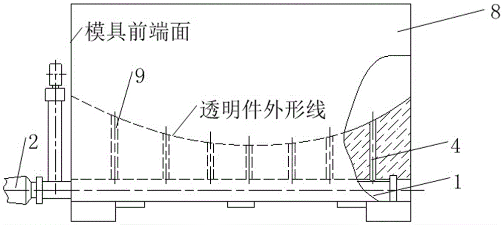
[0029] The vacuum pipeline is installed in the transparent part forming mold 8, the suction pipe 1 is placed ...


PUM


Abstract

The invention relates to a controllable vacuumizing pipeline device for a forming mold for a transparent part of an aircraft, and belongs to the technical field of manufacturing of transparent parts of the aircraft. The controllable vacuumizing pipeline device for the forming mold for the transparent part of the aircraft comprises a vacuum pipeline and a vacuum air extraction device; an air extraction pipe, branch pipes and a bent pipe on the vacuum pipeline are welded integrally; the bent pipe is welded to the front end of the air extraction pipe; a vacuum pressure gauge connector is welded to the other end of the bent pipe; the multiple branch pipes are welded in the radial direction of the air extraction pipe; a metal plug cover is welded to one end of the air extraction pipe; a first pipe connector is welded to the end at the other side of the air extraction pipe; the end surface of the metal plug cover is overlapped with the contour line of the part on the mold; the vacuum pipeline is arranged in the forming mold for the transparent part; the air extraction pipe is placed at the bottom of the forming mold for the transparent part to be fixed and is located on the symmetric surface of the surface of the forming mold for the transparent part; and all the branch pipes are inserted into the forming mold for the transparent part to be formed, namely, in the mold hole, and the end surfaces are leveled according to the molded surface of the forming mold for the transparent part.

Description

technical field [0001] The invention relates to a controllable vacuum pumping pipeline device for a forming mold of an aircraft transparent part, and belongs to the technical field of aircraft transparent part manufacturing. Background technique [0002] The transparent parts of modern aircraft canopy are usually large-scale and observation parts with large curvature, and the molding method is usually the vacuum contact molding method of the female mold. This type of molding process is to place the heated plexiglass blank in the female mold, press the two sides of the glass with a special press frame, and immediately connect the vacuum device, and the air between the glass and the female mold is extracted by the vacuum pipeline and branch pipe. To generate a vacuum pressure difference, and then make the glass adhere to the surface of the mold to complete the molding. The traditional pipeline cannot control the vacuum degree, so that when forming large, thin, and large-curva...

Claims


Application Information

Patent Timeline
Patent Type & Authority Applications(China)
IPC IPC(8): B29C43/56B29K33/04B29L31/30
CPCB29C43/56B29C2043/563B29K2033/12B29L2031/3079
Inventor 高翔郭蕊娜胡建冬
Owner JIANGXI HONGDU AVIATION IND GRP
Learn More