Shockproof thrust clamping device for bearing bush

A technology of thrust clamps and bearing bushes, applied in the direction of workpiece clamping devices, manufacturing tools, etc., can solve the problems of increasing the risk and cost of loss, affecting the use effect, complex process, etc., to reduce processing costs, facilitate disassembly, and process manufacturing The effect of simple process

Inactive Publication Date: 2017-05-31
SHIYAN HANGAO ELECTRICAL & MECHANICAL TECH
View PDF0 Cites 1 Cited by
  • Summary
  • Abstract
  • Description
  • Claims
  • Application Information

AI Technical Summary

Problems solved by technology

The cost of the final product of this production method is slightly lower than that of the integral flanging type thrust bearing, but the process is more complicated, and the burrs generated by riveting and activation must undergo secondary treatment, otherwise the use effect will be affected
For some other detachable thrust-side bearings including this edging bearing, another defect is that the thrust plate cannot be separated from the bearing body after installation due to the riveting process, and the thrust plate appears during the production process. Some defects can lead to the scrapping of the entire bearing bush, increasing the risk and cost of loss

Method used


Image

  • Shockproof thrust clamping device for bearing bush
  • Shockproof thrust clamping device for bearing bush

Examples


Embodiment Construction

[0012] The following will clearly and completely describe the technical solutions in the embodiments of the present invention with reference to the accompanying drawings in the embodiments of the present invention. Obviously, the described embodiments are only some, not all, embodiments of the present invention. Based on the embodiments of the present invention, all other embodiments obtained by persons of ordinary skill in the art without making creative efforts belong to the protection scope of the present invention.

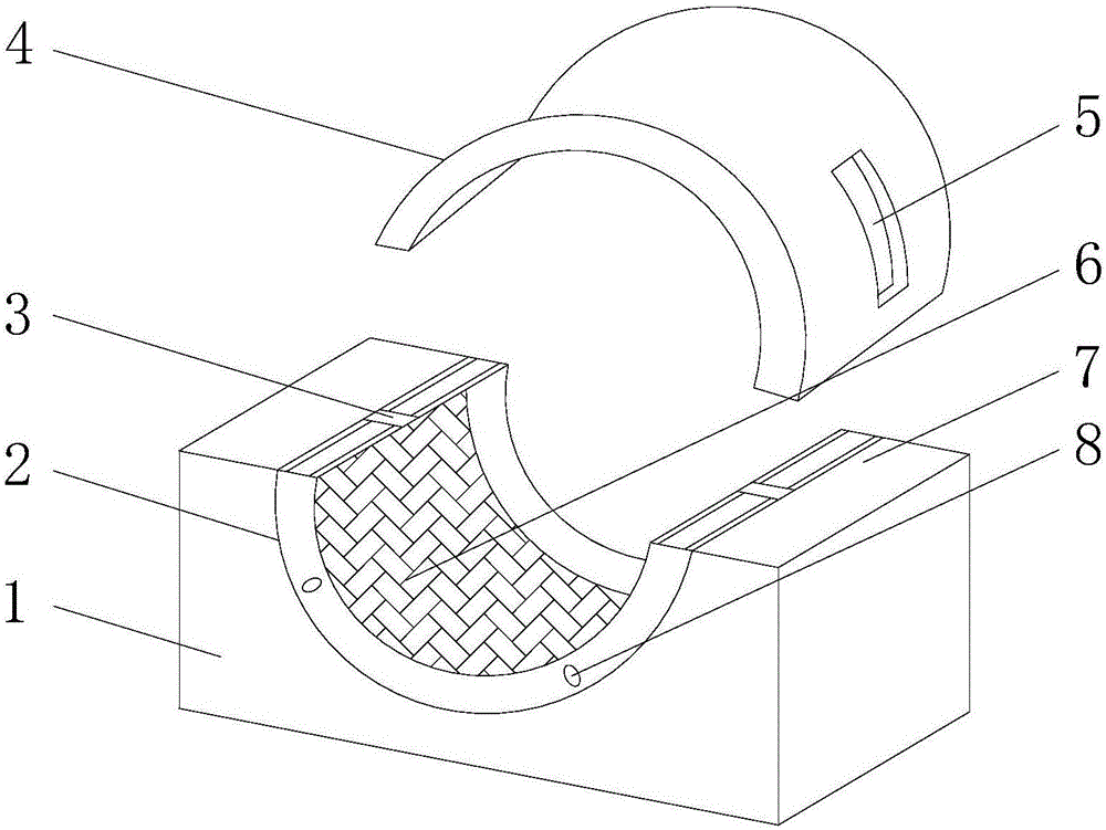
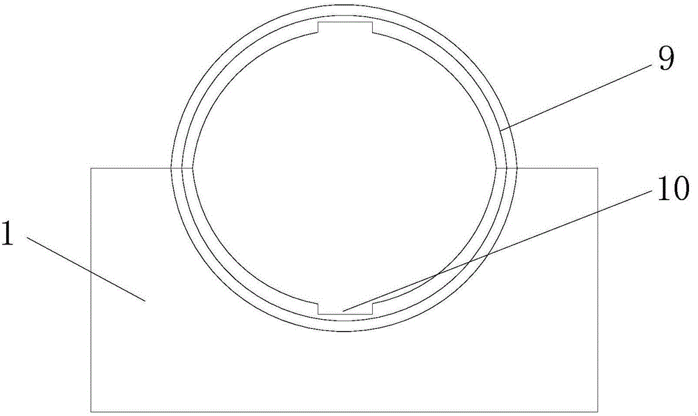
[0013] see figure 1 and figure 2 , an embodiment provided by the present invention: a bearing pad anti-vibration thrust clamping device, including a lower thrust bearing pad 2 and an upper thrust bearing pad 4, both of the lower thrust bearing pad 2 and the upper thrust bearing pad 4 are fixed on the bearing by screws In the cover 1, the lower thrust bearing bush 2, the upper thrust bearing bush 4 and the thrust plate are an integral stamping part, and the t...


PUM


Abstract

The invention discloses a shockproof thrust clamping device for a bearing bush. The device comprises a lower thrust bearing bush and an upper thrust bearing bush; both the lower thrust bearing bush and the upper thrust bearing bush are fixed in a bearing cap through screws; the lower thrust bearing bush, the upper thrust bearing bush and a thrust plate are an integrated stamped part; bayonets are formed in tops and bottoms of the lower thrust bearing bush and the upper thrust bearing bush; shockproof gaskets are arranged inside the lower thrust bearing bush and the upper thrust bearing bush; oil inlets are formed in the left side and the right side of the upper side of the lower thrust bearing bush; oil passing holes are formed in the left side and the right side of the front side of the lower thrust bearing bush; and main oil channels are formed in the left side and the right side of the upper thrust bearing bush and are connected with the oil inlets. According to the device, the machining and manufacturing technology is simple, the machining cost can be reduced, the device is convenient to dismount and maintain, the bearing bush and the thrust plate are fixedly connected together through openings and notches, and the shockproof gaskets are arranged, so that the reliability of an engine is improved.

Description

technical field [0001] The invention relates to the technical field of engine parts, in particular to an anti-vibration and anti-thrust clamping device for a bearing bush. Background technique [0002] At present, the thrust bearing bush is a common accessory for internal combustion engines such as diesel engines and gasoline engines, as well as some transmission machinery, and is also a vulnerable part. With the development of automobiles, construction machinery, and agricultural machinery, the demand for internal combustion engines is increasing, especially for heavy vehicles. With the use and development, the technical requirements for the thrust bearing bush are getting higher and higher. At present, the common thrust bearing bushes are mainly integral flanging type and edge riveting type. The integral flanging type thrust bearing bush has the advantages of good rigidity, convenient installation and high technical precision, but the production cost is the highest, and b...

Claims


Application Information

Patent Timeline
Patent Type & Authority Applications(China)
IPC IPC(8): B21J15/42B25B11/00
CPCB21J15/42B25B11/00
Inventor 赵华斌冯大庆王全侯自毅冯伶誉
Owner SHIYAN HANGAO ELECTRICAL & MECHANICAL TECH
Why Eureka
Try Eureka