
Boiler flue gas recovery device

A technology for recovering equipment and boiler flue gas, applied in lighting and heating equipment, gas treatment, climate sustainability, etc., can solve the problems of low recovery efficiency, improve utilization rate, increase heat exchange contact area, and improve heat exchange efficiency effect

Inactive Publication Date: 2017-05-31
SUZHOU SHUYUE CARBON ADSORBENT CO LTD
View PDF0 Cites 0 Cited by
  • Summary
  • Abstract
  • Description
  • Claims
  • Application Information

AI Technical Summary

Problems solved by technology

[0004] What the present invention needs to solve is the problem of low recovery efficiency of the existing boiler flue gas recovery equipment, and provides a boiler flue gas recovery equipment

Method used

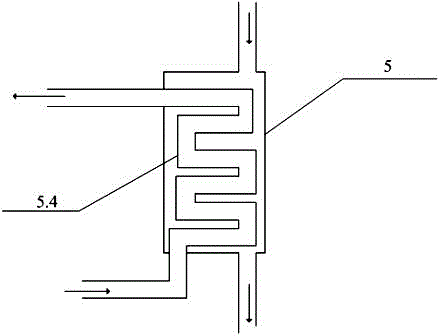
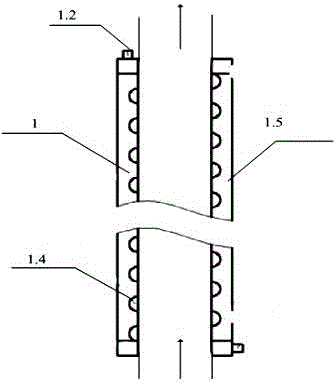

Image

  • Boiler flue gas recovery device
  • Boiler flue gas recovery device
  • Boiler flue gas recovery device

Examples


Embodiment Construction

[0024] The present invention will be further described below in conjunction with embodiment.

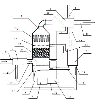
[0025] A boiler flue gas recovery equipment, such as figure 1 As shown, it includes a heat absorber 1, an absorption tower 2, a nitrogen and sulfur recovery device 3, a condensation device 4 and a heat exchanger 5. Mainly through multiple heat absorption, the heat in the exhaust gas is absorbed.

[0026] The input end of the heat absorber 1 is connected to the waste inlet 1.1; the waste outlet 1.3 of the heat absorber 1 is connected to the absorption tower 2; the heat absorber 1 is connected to the hot water outlet 5.1 of the heat converter 5; The input end of the condensation device 4 is connected with the gas output end of the absorption tower 2. The warm water outlet 4.4 of the condensation device 4 is connected to the heat exchanger 5; the gas condensation outlet 4.2 of the condensation device 4 is connected to the absorption tower 2.

[0027] The nitrogen-sulfur miscellaneous...


PUM


Abstract

The present invention provides a boiler flue gas recovery device, and belongs to the field of waste gas treatment equipment. The boiler flue gas recovery device comprises a heat absorber, an absorption tower, a nitrogen and sulfur recovery device, a condenser and a heat converter. An input end of the heat absorber is connected with a waste gas inlet; a waste gas outlet of the heat absorber is connected with the absorption tower; the heat absorber is connected with a hot water outlet of the heat converter; an input end of the condenser is connected with a gas outlet end of the absorption tower; a warm water outlet of the condenser is connected with the heat converter. A gas condensation outlet of the condenser is connected with the absorption tower. A nitrogen-sulfur mixed liquid inlet of the nitrogen and sulfur recovery device is connected with the absorption tower; a nitrogen-sulfur mixed liquid outlet of the nitrogen and sulfur recovery device is connected with the heat converter; and an upper accumulated liquid outlet of the heat converter is connected with the absorption tower.

Description

technical field [0001] The invention relates to the field of waste treatment devices, in particular to boiler flue gas recovery equipment. Background technique [0002] Industrial boilers are currently the main thermal power equipment in my country, and one of the main reasons for the high energy consumption and high pollution during the operation of the boilers is the flue gas emissions from the boilers; On the one hand, it is the direct pollution of flue gas pollutants. At present, there are about 550,000 coal-fired industrial boilers and kilns in China, and the coal consumption accounts for about 1 / 3 of the total annual coal consumption in the country. Problems such as high exhaust gas temperature and high concentration of smoke and dust lead to low boiler operation efficiency and insufficient output. The exhaust heat loss of industrial boilers in my country accounts for 8% to 20% of the heat delivered to boilers. Generally speaking, the design thermal efficiency of cha...

Claims


Application Information

Patent Timeline
IPC IPC(8): B01D53/18B01D47/06F23J15/06F23J15/04
CPCB01D47/06B01D53/18B01D2252/103B01D2257/30B01D2257/40B01D2258/0283F23J15/04F23J15/06F23J2215/10F23J2215/20F23J2217/50Y02E20/30Y02P70/10
Inventor 王龙飞
Owner SUZHOU SHUYUE CARBON ADSORBENT CO LTD
Learn More