
Novel corn cob granary

A technology of corn cobs and stacks, which is applied in the field of new corn cobs stacks, can solve the problems of insufficient drying time for corn cobs, poor ventilation and heat dissipation, and moldy corn cobs.

Active Publication Date: 2017-05-31
蒙城县立至信安全技术咨询服务有限公司
View PDF5 Cites 1 Cited by
  • Summary
  • Abstract
  • Description
  • Claims
  • Application Information

AI Technical Summary

Problems solved by technology

Most of the corn in the countryside has a large area of ​​corn, and the amount of corn harvested each time is relatively large, which results in insufficient drying time for corn cobs, resulting in relatively high moisture content in corn. In rural areas, people often use corn cobs The corn cobs are stored in the stack, but the corn cobs are in the middle of the stack, and the corn cobs inside are often moldy due to poor ventilation and heat dissipation. Sometimes people use the top of the stack for better ventilation of the corn cobs in the stack. In the open air, when it rains and snows, if people cannot cover the tarpaulin in time, this will also cause water to enter the stack, which will further accelerate the mold of the corn cobs in the stack, which will bring huge economic losses to farmers. In order to let the corn cobs in the stack For better ventilation, to avoid moldy corn cobs, and to prevent economic losses for farmers, we urgently need a new type of corn cob stack, but there is no such new type of corn cob stack on the market at present

Method used


Image

  • Novel corn cob granary
  • Novel corn cob granary
  • Novel corn cob granary

Examples


Embodiment Construction

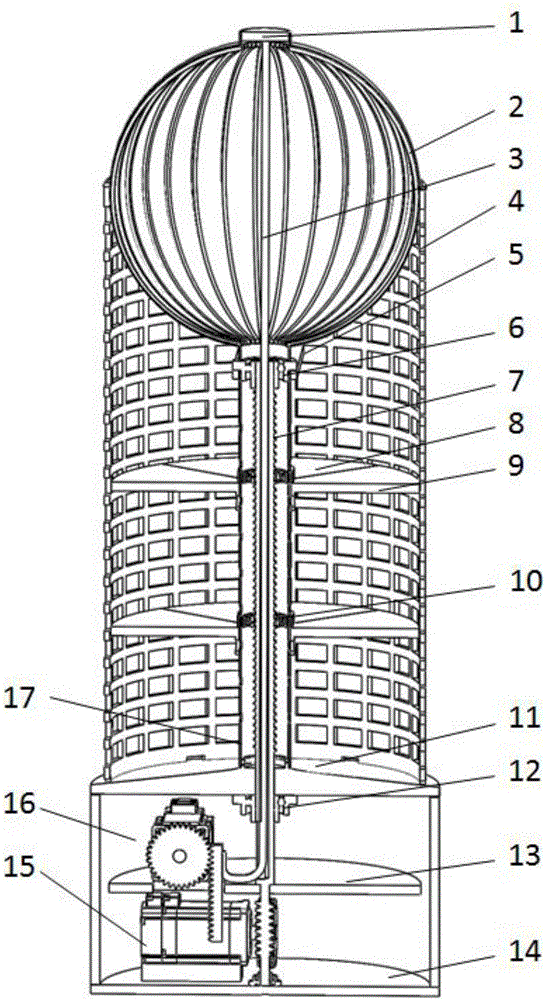
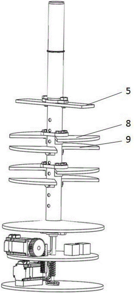
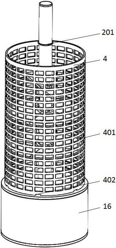
[0026] Such as Figure 1-11 As shown, a new type of corncob stack includes a top cover 1, a rain and snow sensor 101, a rain shielding device 2, a rain shielding ring 201, a retractable rod 202, a lower bracket 203, an upper bracket 204, a waterproof cloth 205, a pull rod 3, Stack 4, grid 401, drainage hole 402, connecting plate 5, first base 6, lead screw 7, moving plate 8, moving plate circular hole 801, moving plate arc plate 802, fixed plate 9, fixed plate arc Plate 901, fixed plate round hole 902, lead screw nut 10, lead screw nut round hole 1001, ring hole 1002, chassis 11, chassis round boss 1101, chassis round hole 1102, second base 12, rotating disc 13, bottom Frame 14, driving device 15, gear 1501, rack 1502, first stepper motor 1503, second stepper motor 1504, worm gear 1505, worm screw 1506, shell 16, inner barrel 17, inner barrel round hole 1701, inner barrel internal thread 1702, The controller 18, the power supply 19, and the third base 20 are characterized in ...


PUM


Abstract

Disclosed is a novel corn cob granary. The invention belongs to the field of agricultural machinery. The novel corn cob granary comprises a top cover, a rain and snow sensor, a rain device, a tie rod, a connecting plate, a screw rod, a movable plate, a fixing plate, a screw nut, a driving device, a case, an inner barrel, a controller, a power supply and the like. The novel corn cob granary is characterized in that the top cover is fixed to the upper end of the rain device, the rain and snow sensor is fixed on the top cover, the screw rod and the screw nut are matched, the screw nut and the movable plate are fixed together by bolts, the fixing plate and the inner barrel are fixed together through screws, the lower end of the inner barrel and a chassis are fixed together, a chassis circular hole is formed in the chassis by processing, the lower end of the screw rod penetrates through the chassis circular hole to be fixed to a rotary disc, and the screw rod is matched with the chassis through a second base in a rotation mode; the upper end of a worm and the lower end of the screw rod are fixed together, the upper end of the tie rod is fixed on the top cover, the lower end of the tie rod and a rack are fixed together, and the power supply and the controller are fixed on the rotary disc. The novel corn cob granary has the function that corn cobs move up and down in the granary, and achieves the purposes of ventilation and mildew prevention.

Description

technical field [0001] The present invention relates to a new type of corn cob stack, in particular it uses a top cover, a rain and snow sensor, a rain shielding device, a pull rod, a stack, a connecting plate, a first base, a lead screw, a moving plate, a fixed plate, and a lead screw The utility model relates to a novel corn cob stack composed of a nut, a chassis, a second base, a rotating disc, a base frame, a driving device, a casing, an inner bucket, a controller, a power supply, and a third base, belonging to the agricultural machinery category. Background technique [0002] Corn has always been the leading force in my country's agricultural market. As my country's second largest food crop, it ranks among the best in the world. Most of the corn in the countryside has a large area of ​​corn, and the amount of corn harvested each time is relatively large, which results in insufficient drying time for corn cobs, resulting in relatively high moisture content in corn. In ru...

Claims


Application Information

Patent Timeline
IPC IPC(8): A01F25/14A01F25/22
CPCA01F25/14A01F25/22Y02A40/51
Inventor 胥曰强莫玉军曹虎
Owner 蒙城县立至信安全技术咨询服务有限公司
Learn More