
Pairing dual-contact connector and PCB board connection structure

A PCB board and double-contact technology, which is applied in the direction of connection, parts of the connection device, contact parts, etc., can solve problems such as unstable connection, inconvenient operation, and complicated structure, and achieve convenient and stable electrical connection and simple structure Effect

Active Publication Date: 2017-05-24
XIAMEN GUANG WANG IND
View PDF6 Cites 0 Cited by
  • Summary
  • Abstract
  • Description
  • Claims
  • Application Information

AI Technical Summary

Problems solved by technology

The wire connection is very inconvenient to operate, and it is prone to disconnection
Compared with wire connection, connector connection has certain advantages. However, there are many types of existing connectors and their structures are also different. Different connectors have more or less disadvantages, and some structures are more complicated. , some connections are not stable

Method used


Image

  • Pairing dual-contact connector and PCB board connection structure
  • Pairing dual-contact connector and PCB board connection structure
  • Pairing dual-contact connector and PCB board connection structure

Examples


Embodiment 1 2

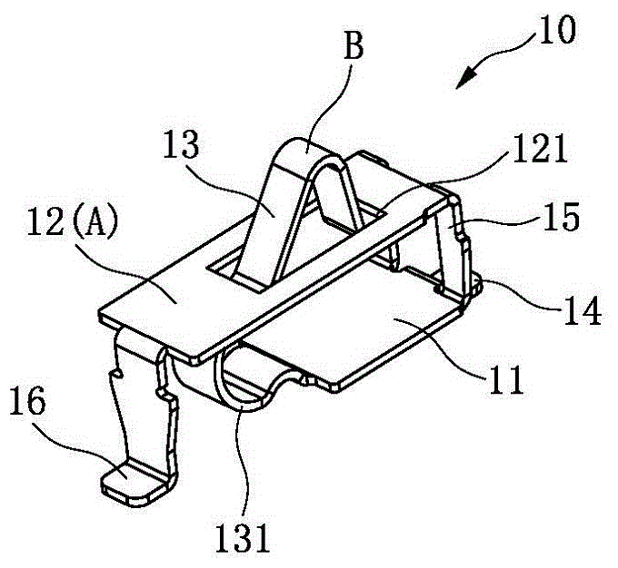
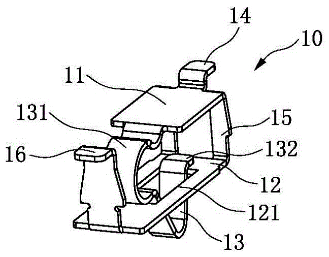
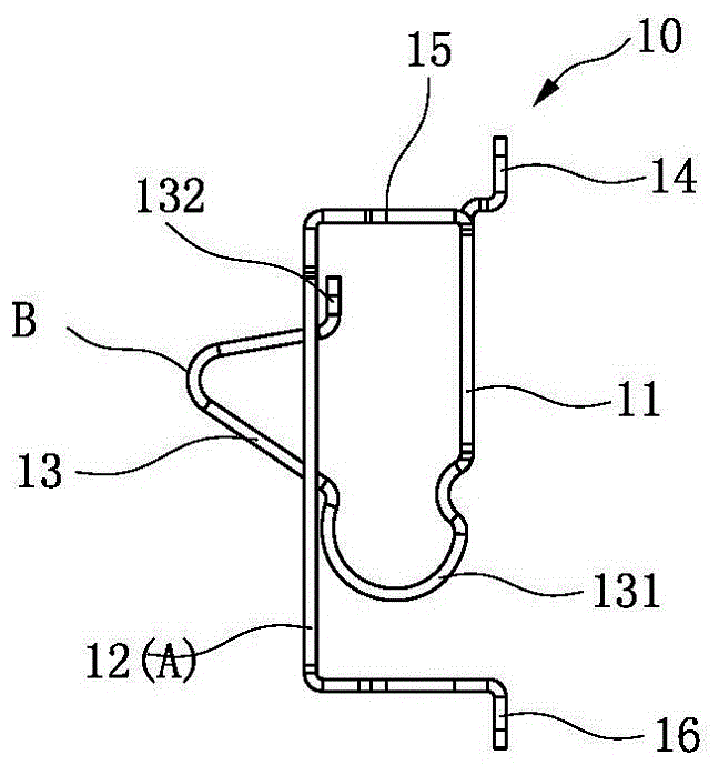
[0035] Embodiments 1 and 2: the lower substrate 11 is short and the upper elastic plate 12 is long, and the other end of the substrate 11 under the frame body 10 forms a first electrical pin 14 outward (the first embodiment is a welding leg, and the second embodiment is a pin) , the other end of the base plate 11 under the frame body 10 forms a bracket 15 upwards, the upper end of the bracket 15 is connected to the other end of the upper elastic plate 12, and the upper elastic plate 12 covers the lower base plate 11 and the elastic piece 13, because the upper elastic plate 12 is long enough , the upper elastic plate 12 corresponds to the second contact B to form a through hole 121 for the second contact B to pass through, and one end of the upper elastic plate 12 is bent downward to form a second electrical pin 16 (the first embodiment is a welding leg, the implementation Example 2 is a pin), the elastic piece 13 extending from one end of the substrate 11 under the frame body 1...

Embodiment 3 4

[0037] Embodiments 3 and 4: the lower substrate 11 is long and the upper elastic plate 12 is short, and the other end of the substrate 11 under the frame body 10 forms a first electrical pin 14 outward (the third embodiment is a welding leg, and the fourth embodiment is a pin) The other end of the base plate 11 under the frame body 10 forms a bracket 15 upwards, and the upper end of the bracket 15 is connected to the other end of the upper elastic plate 12, because the upper elastic plate 12 is relatively short, and the elastic piece 13 extending from one end of the base plate 11 under the frame body 10 A hook 132 is formed at the end, which can just be hooked on one end edge of the upper elastic plate 12 to limit the position of the elastic piece 13 .

[0038] The double-contact connector 100 of the third and fourth embodiments can be equipped with a rubber core 20, which can facilitate the side-by-side assembly of multiple double-contact connectors 100. The rubber core 20 is ...


PUM


Abstract

The invention discloses a pairing dual-contact connector which comprises a frame body. An electrical pin (weld leg or pin) is formed on the frame body. The frame body is provided with a lower substrate and an upper elastic board. The upper surface of the upper elastic board is used as a first contact. An elastic piece extends from one end of the lower substrate. The elastic piece is bent upwards and then bent down to form a second contact at a turning part. The first contact and the second contact are arranged side by side. The invention further discloses a PCB board connection structure. Dual-contact connectors are arranged on two PCB boards respectively. When two PCB boards are in butt joint, the second contact of the elastic piece of one dual-contact connector abuts against the first contact of the upper elastic board of the other dual-contact connector, and at the same time the first contact of the upper elastic board of one dual-contact connector abuts against the second contact of the elastic piece of the other dual-contact connector to realize dual-contact connection. According to the invention, the structure is simple, and electrical connection is convenient, stable and reliable.

Description

technical field [0001] The invention relates to the technical field of connectors, in particular to a double-contact connector suitable for pairing and a connection structure of two PCB boards. Background technique [0002] In the prior art, the electrical connection between two PCB boards is either connected by wires or connected by means of connectors (such as mating between male ends and female ends). Wire connection is very inconvenient to operate, and it is prone to disconnection. Compared with wire connection, connector connection has certain advantages. However, there are many types of existing connectors and their structures are also different. Different connectors have more or less disadvantages, and some structures are more complicated. , and some connections are not stable. Contents of the invention [0003] An object of the present invention is to provide a double-contact connector suitable for pairing and a connection structure for two PCB boards, which has ...

Claims


Application Information

Patent Timeline
Patent Type & Authority Applications(China)
IPC IPC(8): H01R12/71H01R13/24
CPCH01R12/716H01R13/24H01R13/2492
Inventor 陈炳水
Owner XIAMEN GUANG WANG IND
Learn More