
A glue constant temperature system

A constant temperature system and glue technology, which is applied in the direction of using electric means for temperature control, auxiliary controller with auxiliary heating device, etc., can solve the problems such as the performance degradation of storage glue, uneven gluing of limit plates, and reduced product quality. , to achieve the effect of good control and regulation, improve the stirring effect, and improve the stirring efficiency.

Active Publication Date: 2018-08-28
成都建丰新材料股份有限公司
View PDF5 Cites 0 Cited by
  • Summary
  • Abstract
  • Description
  • Claims
  • Application Information

AI Technical Summary

Problems solved by technology

[0002] The existing glue is directly stored in the storage tank after the production and preparation is completed, and it is used directly when it is ready to be used. Glue plays a vital role in the production process of impregnated paper. The performance of the glue directly affects the quality of the impregnated paper. Quality, but in winter and summer, during the dipping production process, the high-fraction premix formed by glue and white corundum will cause uneven glue coating on the paper surface due to the viscosity change caused by temperature; Partial precipitation occurs at the bottom, and there are differences in the upper and lower concentrations of the glue. During use, the concentration difference will lead to differences in glue application, resulting in uneven glue application on the limit plate, which will lead to the existence of a large number of defective impregnated paper. , greatly reducing the quality of the product, therefore, if ensuring the constant temperature of the produced glue is to solve the main problem of the decline in the performance of the stored glue

Method used


Image

  • A glue constant temperature system
  • A glue constant temperature system
  • A glue constant temperature system

Examples


Embodiment Construction

[0018] In order to enable those skilled in the art to better understand the technical solution of the present invention, the technical solution of the present invention will be further described below in conjunction with the accompanying drawings and embodiments.

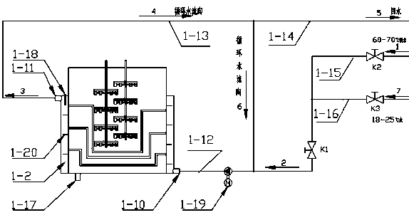
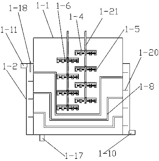
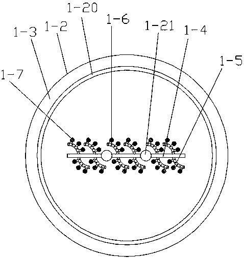
[0019] Refer to attached Figure 1-4 A glue constant temperature system shown includes a glue tank 1-1, the bottom of the glue tank 1-1 is also provided with a discharge port 1-17, and the outside of the glue tank 1-1 is provided with a jacket layer 1-1 surrounding it. 2. A temperature-regulating cavity 1-3 is formed between the glue tank 1-1 and the jacket layer 1-2, and an inner wall guide spirally wound on the glue tank 1-1 is arranged in the temperature-regulating cavity 1-3. flow plate 1-20, the inside of the glue tank 1-1 is provided with a multi-layer central synchronous temperature control tube 1-8, and the two ends of each central synchronous temperature control tube 1-8 are connected with the jacket The t...


PUM


Abstract

The invention discloses a constant-temperature system of glue. The constant-temperature system comprises a glue tank, wherein a jacket layer which surrounds the glue tank is arranged outside the glue tank, a temperature adjusting cavity is formed between the glue tank and the jacket layer, an inner wall diversion plate which is spirally coiled on the glue tank is arranged in the temperature adjusting cavity, a plurality of layers of center-synchronized temperature adjusting tubes are arranged in the glue tank, both ends of each center-synchronized temperature adjusting tube are communicated with the temperature adjusting cavity of the jacket layer, and an efficient stirrer is arranged in the glue tank. According to the constant-temperature system, the jacket type glue tank is adopted, hot water is circulated, the temperature is automatically controlled, and the temperature fluctuation range is less than 1 DEG C. The product stability is increased, the structure is simple, the cost is low, the temperature control effect of the glue is good, the adjustment is quick, the efficiency is high, the glue can be directly used in various environments every season, and the performance of the glue is the same as that of the glue which is newly produced.

Description

technical field [0001] The invention relates to a glue constant temperature system. Background technique [0002] The existing glue is directly stored in the storage tank after the production and preparation is completed, and it is used directly when it is ready to be used. Glue plays a vital role in the production process of impregnated paper. The performance of the glue directly affects the quality of the impregnated paper. Quality, but in winter and summer, during the dipping production process, the high-fraction premix formed by glue and white corundum will cause uneven glue coating on the paper surface due to the viscosity change caused by temperature; Partial precipitation occurs at the bottom, and there are differences in the upper and lower concentrations of the glue. During use, the concentration difference will lead to differences in glue application, resulting in uneven glue application on the limit plate, which will lead to the existence of a large number of defe...

Claims


Application Information

Patent Timeline
Patent Type & Authority Patents(China)
IPC IPC(8): G05D23/32
CPCG05D23/32
Inventor 彭荣钟和松李加龙杨杰
Owner 成都建丰新材料股份有限公司
Learn More