Laser microwave reflective mirror control device

A microwave reflection and control device technology, applied in installation, optics, optical components, etc., can solve the problems of difficult movement and large volume, and achieve the effects of simple equipment, wide application range and convenient control

Inactive Publication Date: 2017-05-24
合肥亿福自动化科技有限公司
View PDF0 Cites 1 Cited by
  • Summary
  • Abstract
  • Description
  • Claims
  • Application Information

AI Technical Summary

Problems solved by technology

[0005] However, the existing lasers change the laser emission direction by moving the laser emitter. However, due to the relatively large volume of some high-power laser emitters, it is relatively difficult to move. A new method is needed to control the emission direction.

Method used


Image

  • Laser microwave reflective mirror control device
  • Laser microwave reflective mirror control device
  • Laser microwave reflective mirror control device

Examples


Embodiment Construction

[0018] Below in conjunction with embodiment the present invention will be further described, but the present invention is not limited to these examples, under the premise of departing from the gist of the present invention, any improvement made falls within the protection scope of the present invention.

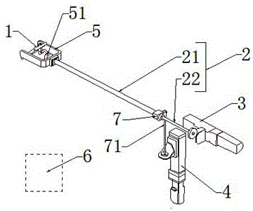
[0019] As shown in the figure, a laser microwave reflective mirror control device according to the present invention includes a reflective mirror 1, a mirror push rod 2, a polar motor 3, a hoop motor 4 and a controller 6. On the reflective mirror 2 Fitted with a U-shaped bracket 5, two opposite sides of the mirror surface 1 are fixed on the U-shaped bracket 5 through a rotating shaft and a bearing, and the mirror push rod 2 includes a concentric polar push rod 22 and a ring To the push rod 21, the annular push rod 21 is connected to the bottom of the U-shaped support 5, and the polar push rod 22 is connected to the back of the mirror surface 1 through the connector 51, and is ...


PUM


Abstract

The invention provides a laser microwave reflective mirror control device. The device comprises a reflective mirror, a mirror push rod, a polarity motor, a circumference motor and a controller, wherein a U-shaped bracket is arranged on the reflective mirror; two opposite edges on the reflective mirror are fixed on the U-shaped bracket through a rotating shaft and a bearing; the mirror push rod comprises a homocentric polarity push rod and a circumference push rod; the circumference push rod is connected with the bottom of the U-shaped bracket; the polarity push rod is connected with the back of the reflective mirror through the connecting piece, and is used for controlling the reflective mirror to overturn on the U-shaped bracket; the polarity motor is connected with the polarity push rod; the circumference motor is connected with the circumference push rod through a screw and a gear box and is vertical to the circumference push rod; and coders are arranged in the polarity motor and the circumference motor. The laser microwave reflective mirror control device can overcome defects in the prior art, can be used for calculating the direction of reflected laser by detecting the position of a step motor, is convenient and accurate to control, is simple in equipment and convenient to maintain, and has a wide application range.

Description

technical field [0001] The invention relates to the technical field of laser microwave emission angles, in particular to a laser microwave reflection mirror control device. Background technique [0002] Laser is another major invention of mankind since the 20th century, following atomic energy, computers, and semiconductors. It is called "the fastest knife", "the most accurate ruler", and "the brightest light". [0003] Light is emitted from the atoms that make up the matter. After the atoms gain energy, they are in an unstable state (that is, an excited state), and it emits energy in the form of photons. And the laser is the induced (excited) photon queue, the photons in this photon queue have the same optical characteristics, and their steps are extremely consistent. For example, the photons emitted by ordinary light sources, such as light bulbs, are different, and they will run around in all directions, which is very disunity, but the photons in the laser are thinking in...

Claims


Application Information

Patent Timeline
Patent Type & Authority Applications(China)
IPC IPC(8): G02B7/182
CPCG02B7/182
Inventor 汪根生任小体游锦山王勇武鹏程张鹏
Owner 合肥亿福自动化科技有限公司
Why Eureka
Try Eureka