
Method of simulating generating of large depth field programmable grating

A grating and depth-of-field technology, applied in the field of optical detection, can solve the problems of limited three-dimensional measurement range, fixed projection pattern, inflexible use, etc., to achieve the effect of improving three-dimensional measurement accuracy, expanding depth of field, and improving measurement range

Active Publication Date: 2017-05-24
XIAN CHISHINE OPTOELECTRONICS TECH CO LTD
View PDF6 Cites 9 Cited by
  • Summary
  • Abstract
  • Description
  • Claims
  • Application Information

AI Technical Summary

Problems solved by technology

But the disadvantage of physical grating is that the projection pattern is fixed and the use is not flexible
In addition, no matter the analog pattern of digital light projection technology or physical grating projection, it is an image of the film, which is an imaging relationship, so there is a limitation of depth of field
Greatly limits the range of 3D measurements

Method used


Image

  • Method of simulating generating of large depth field programmable grating
  • Method of simulating generating of large depth field programmable grating
  • Method of simulating generating of large depth field programmable grating

Examples


Embodiment Construction

[0039]The present invention will be described in detail below in conjunction with the accompanying drawings.

[0040] The technical solution is:

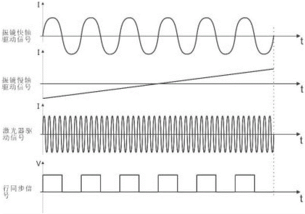
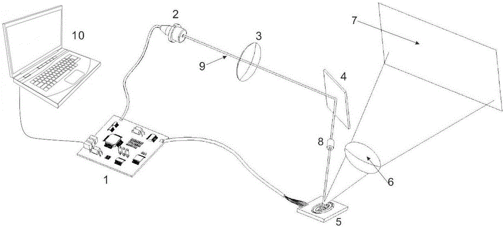
[0041] The first step is to design the working parameters of the system. Determine the maximum working distance L according to the working distance of the grating 2 , the minimum working distance L 1 ; the maximum spot ω of ΔL within the depth of field max ; The number M of lines scanned by a single frame raster image, M is determined by the characteristics of the laser beam.

[0042] The second step is to generate the driving signal. There are three types of drive signals involved. 1) MEMS scanning galvanometer fast axis drive signal, which is a current signal of sine (or cosine) waveform, its frequency f x Equal to the resonant frequency f of the fast axis direction of the MEMS scanning galvanometer, its peak-to-peak value I x峰峰 Determined by the parameters of the MEMS galvanometer. 2) The slow axis drive signal of the MEM...


PUM


Abstract

The invention discloses a method of simulating generating of large depth field programmable grating. A laser is used to emit a laser beam, and after focusing and collimating of a collimating lens, a collimating Gaussian laser beam capable of satisfying requirements is acquired. After primary specular reflection, the laser beam passes through a circular diaphragm, and is emitted into an MEMS vibration mirror. The laser beam is reflected to a surface of a measured object by the MEMS vibration mirror. Under control of a sinusoidal current signal generated by a driving board, the laser is used for the sinusoidal modulation of the brightness of the laser beam. Under excitation of a driving signal generated by the driving board, the MEMS vibration mirror is used for two-dimensional rotation, and therefore the laser beam is driven to carry out scanning, and grating images are generated. The cycle and the phase of the driving signal of the laser are changed to acquire the grating images of different cycles and different phases. The grating generated by adopting the above mentioned technical scheme has a programmable advantage of a digital grating and a high resolution advantage of a physical grating. The field depth of the generated grating is extended by more than ten times, and therefore a measuring range is greatly improved.

Description

Technical field: [0001] The invention belongs to the field of optical detection, and relates to a method for generating a grating, in particular to a method for generating a programmable analog grating with a large depth of field. Background technique: [0002] As a bridge between the real world and the virtual digital world, 3D measurement technology plays an increasingly important role. It is widely used in many industries such as industrial inspection, medical health, digital entertainment, e-commerce, cultural relics protection, etc. Due to the advantages of non-contact, high precision and fast speed, optical three-dimensional measurement has developed into the most important technology in the field of three-dimensional inspection. Optical three-dimensional measurement can be divided into two types: active and passive. Passive measurement methods are represented by stereo vision. However, the stereoscopic vision technology system is simple in structure and low in cost...

Claims


Application Information

Patent Timeline
Patent Type & Authority Applications(China)
IPC IPC(8): G01B11/25
CPCG01B11/2536G02B26/101G02B27/0075G01B11/2518G02B26/0833G02B27/30
Inventor 杨涛金瑞李泉刘涛马力黄军旗
Owner XIAN CHISHINE OPTOELECTRONICS TECH CO LTD
Learn More