A pay-off reel for automatic assembly of detonators

An automatic assembly and pay-off reel technology, applied in the direction of offensive equipment, fuzes, weapon accessories, etc., to achieve the effect of reducing production operators, reducing labor intensity, and compact equipment

Active Publication Date: 2018-11-23
深圳金源恒业科技有限公司
View PDF4 Cites 0 Cited by
  • Summary
  • Abstract
  • Description
  • Claims
  • Application Information

AI Technical Summary

Problems solved by technology

[0008] The purpose of the present invention is to provide a firing element pay-off reel for the automatic assembly of industrial detonators to solve the technical problem that the firing element and the basic detonator can be accurately docked and assembled to complete the bayonet on the automatic assembly production line

Method used


Image

  • A pay-off reel for automatic assembly of detonators
  • A pay-off reel for automatic assembly of detonators
  • A pay-off reel for automatic assembly of detonators

Examples


Embodiment Construction

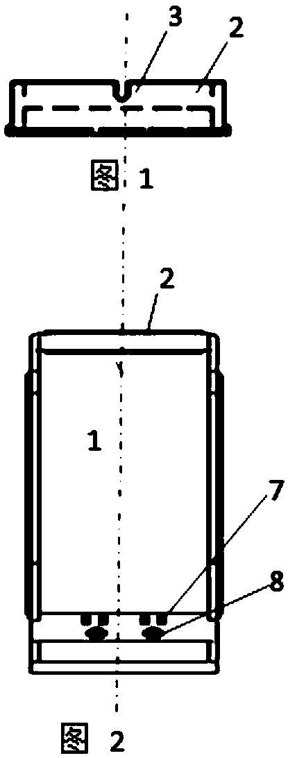
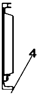
[0060] The shape of the present invention is a regular rectangular tray 1, the outer edge of the rectangular tray is provided with a convex frame 2 on opposite sides or around it, and at least one set of pluggable devices 3 is provided on one side of the convex frame 2, if there is a concave shape with a clamping and positioning function Clips or elastic "U"-shaped clips; the edge of the rectangular tray is symmetrically opposite to the side where the jamming device 3 is provided, and a push-pull boss 4 is provided on the edge of the rectangular tray for each working station mechanical device to push or pull out the pay-off reel; The inner side of the rectangular tray on one side of the jamming device 3 is provided with a clamping groove 5 for fixing the lead wire; a branch line frame 6 is provided in the rectangular tray; a link electric detonator or digital electronic device is provided in the rectangular tray on the opposite side of the jamming device 3 . The clamp (or colum...


PUM


Abstract

The invention discloses a pay-off spool used for automatically assembling detonators. The pay-off spool comprises a rectangular tray, protruding frames, clamping and plugging devices, wire clamping grooves, a push-pull protruding frame, wire supporting frames, wire clamps (or columns) and test poles. The protruding frames are arranged on at least two sides, in the opposite directions, of the rectangular tray. The clamping and plugging devices are arranged on the protruding frame on one side of the special tray. The clamping and plugging devices are in the form of single-U-shaped metal sheets or double-U-shaped metal sheets or elastic U-shaped metal clamps or the combination of two or more of the single-U-shaped metal sheets, the double-U-shaped metal sheets and the elastic U-shaped metal clamps, and are all arranged in the outer side direction of the frames. When the pay-off spool is used for the electric detonators or the electronic detonators, the wire clamps (or the columns) and the test poles are arranged on the portions, in the opposite direction corresponding to the side provided with the clamping and plugging devices, on the inner side of the tray, and each wire clamp (or column) and the corresponding test pole are connected or integrated. The pay-off spool can solve the technical problem that electric firing elements or cartridge igniters can be accurately assembled together with the basic detonators in a butt joint manner on an automatic assembly production line to complete clipping.

Description

technical field [0001] The invention belongs to the field of detonator production equipment, and relates to a device for automatic assembly and production of industrial detonators. Background technique [0002] Detonators are generally divided into electric detonators and nonel detonators. The production process of detonators is usually divided into two steps: loading and assembly. Filling is to press various pyrotechnic agents and parts into the detonator shell to make the basic detonator; the main process of assembly production includes bayonet, electric inspection or injection of digital information, coding, etc., bayonet is to put the ignition element (divided into Electric ignition element or non-electric detonator) are firmly combined with the basic detonator. The electric inspection is to detect whether the resistance value of the electric detonator is within the qualified range through a special instrument. The code is to engrave a set of codes on the shell of the de...

Claims


Application Information

Patent Timeline
Patent Type & Authority Patents(China)
IPC IPC(8): F42C19/08
CPCF42C19/08
Inventor 杨祖一王吉顺
Owner 深圳金源恒业科技有限公司
Why Eureka
Try Eureka