
Pipeline gas pressure and flow stabilization device

A technology of gas pressure stabilizing and flow stabilizing device, which is applied in pipeline system, fluid flow, gas/liquid distribution and storage, etc. It can solve the problems that the aerodynamic parameters are very difficult and in the same range, so as to eliminate the influence of gas swirl, Reduce the effect of temperature difference and reduce pressure

Active Publication Date: 2019-02-01
CHINA NORTH ENGINE INST TIANJIN
View PDF7 Cites 0 Cited by
  • Summary
  • Abstract
  • Description
  • Claims
  • Application Information

AI Technical Summary

Problems solved by technology

The turbocharger for ordinary road vehicles has a maximum speed of 100,000 rpm to more than 200,000 rpm, and the average gas flow rate in the pipeline reaches 100m / s~200m / s, corresponding to the pipeline diameter of the compressor It is 30mm~60mm. Although the speed of non-road superchargers such as construction machinery is reduced to tens of thousands of revolutions per minute, the average flow rate of gas in the pipeline is still in the same range, and it is very difficult to accurately measure the aerodynamic parameters.

Method used


Image

  • Pipeline gas pressure and flow stabilization device
  • Pipeline gas pressure and flow stabilization device

Examples


Embodiment Construction

[0024] It should be noted that, in the case of no conflict, the embodiments of the present invention and the features in the embodiments can be combined with each other.

[0025] In describing the present invention, it should be understood that the terms "center", "longitudinal", "transverse", "upper", "lower", "front", "rear", "left", "right", " The orientations or positional relationships indicated by "vertical", "horizontal", "top", "bottom", "inner" and "outer" are based on the orientations or positional relationships shown in the drawings, and are only for the convenience of describing the present invention and Simplified descriptions, rather than indicating or implying that the device or element referred to must have a particular orientation, be constructed and operate in a particular orientation, and thus should not be construed as limiting the invention. In addition, the terms "first", "second", etc. are used for descriptive purposes only, and should not be understood ...


PUM


Abstract

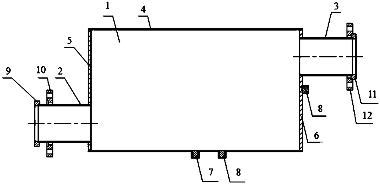
The invention provides a pressure and flow stabilizing device of a pipeline gas. The pressure and flow stabilizing device comprises a pressure and flow stabilizing barrel, a gas inlet pipe and an exhaust pipe, wherein the pressure and flow stabilizing barrel comprises a barrel body and a first end plate and a second end plate which are respectively arranged on the two end faces of the barrel body; the gas inlet pipe is arranged on the lower side of the first end plate; the exhaust pipe is arranged on the upper side of the second end plate; the gas inlet pipe and the exhaust pipe communicate with the pressure and flow stabilizing barrel; and a pressure measurement hole and a temperature measurement hole are formed in the surface of the pressure and flow stabilizing barrel. The pressure and flow stabilizing device has the beneficial effects that a gas flow pressure and flow stabilizing unit is composed of the large-diameter and eccentric pressure and flow stabilizing barrel, and gas flow at the high speed from tens of meters per second to hundreds of meters per second is changed to gas flow at the low speed of 15 meters per second or below, so that a dynamic temperature head and a dynamic pressure head are greatly decreased, and the gas cyclone influence is greatly eliminated; and besides, through mixing flow in the pressure and flow stabilizing barrel, the influence of temperature difference of a central layer and an outer layer of a gas pipeline is reduced, and measurement errors of pressure and temperature of the high-speed flow gas are decreased.

Description

technical field [0001] The invention belongs to the technical field of voltage and flow stabilization control, and in particular relates to a pipeline gas pressure and flow stabilization device. Background technique [0002] The gas turbine performance test is the basis for obtaining its actual performance data and verifying its design. The performance test device and measurement technology of the turbomachine directly affect the accuracy and reliability of the performance test data. In the turbocharger performance test, the performance parameters are mainly obtained through the measurement of the aerodynamic parameters at the inlet and outlet of the turbocharger, and the aerodynamic parameters mentioned here mainly refer to the total temperature, total pressure and static pressure. [0003] Taking compressor efficiency parameters as an example, the efficiency calculated by measuring temperature and pressure ratio (ratio of pressure) is as follows: [0004] [0005] The...

Claims


Application Information

Patent Timeline
Patent Type & Authority Patents(China)
IPC IPC(8): F15D1/02F17D3/01F16L55/02F01D25/00
CPCF01D25/00F16L55/02F17D3/01
Inventor 何洪辛鸿田伟闫瑞乾
Owner CHINA NORTH ENGINE INST TIANJIN
Learn More