
Centrifugal pumps, impellers for convenient measurement of pressure pulsation of centrifugal pump blades

A technology for convenient measurement and vane pressure, which is applied to parts, pumps, and pump components of pumping devices used for elastic fluids, and can solve problems such as the inability to easily measure the pressure pulsation of centrifugal pump vanes, to prevent detachment from the impeller, reduce The effect of small fluid disturbances

Active Publication Date: 2018-12-14
CHINA AGRI UNIV
View PDF6 Cites 0 Cited by
  • Summary
  • Abstract
  • Description
  • Claims
  • Application Information

AI Technical Summary

Problems solved by technology

[0005] The purpose of the present invention is to provide an impeller for conveniently measuring the pressure pulsation of centrifugal pump blades, and a centrifugal pump using the impeller, so as to overcome the defect that the prior art cannot conveniently measure the pressure pulsation on the centrifugal pump blades

Method used


Image

  • Centrifugal pumps, impellers for convenient measurement of pressure pulsation of centrifugal pump blades
  • Centrifugal pumps, impellers for convenient measurement of pressure pulsation of centrifugal pump blades
  • Centrifugal pumps, impellers for convenient measurement of pressure pulsation of centrifugal pump blades

Examples


Embodiment 2

[0032] This embodiment is basically the same as Embodiment 1. For the sake of brevity, in the description process of this embodiment, the same technical features as Embodiment 1 will not be described, and only the differences between this embodiment and Embodiment 1 will be described:

[0033] The centrifugal pump provided in this embodiment uses the impeller described in Embodiment 1, which can conveniently measure the blade pulsation pressure.

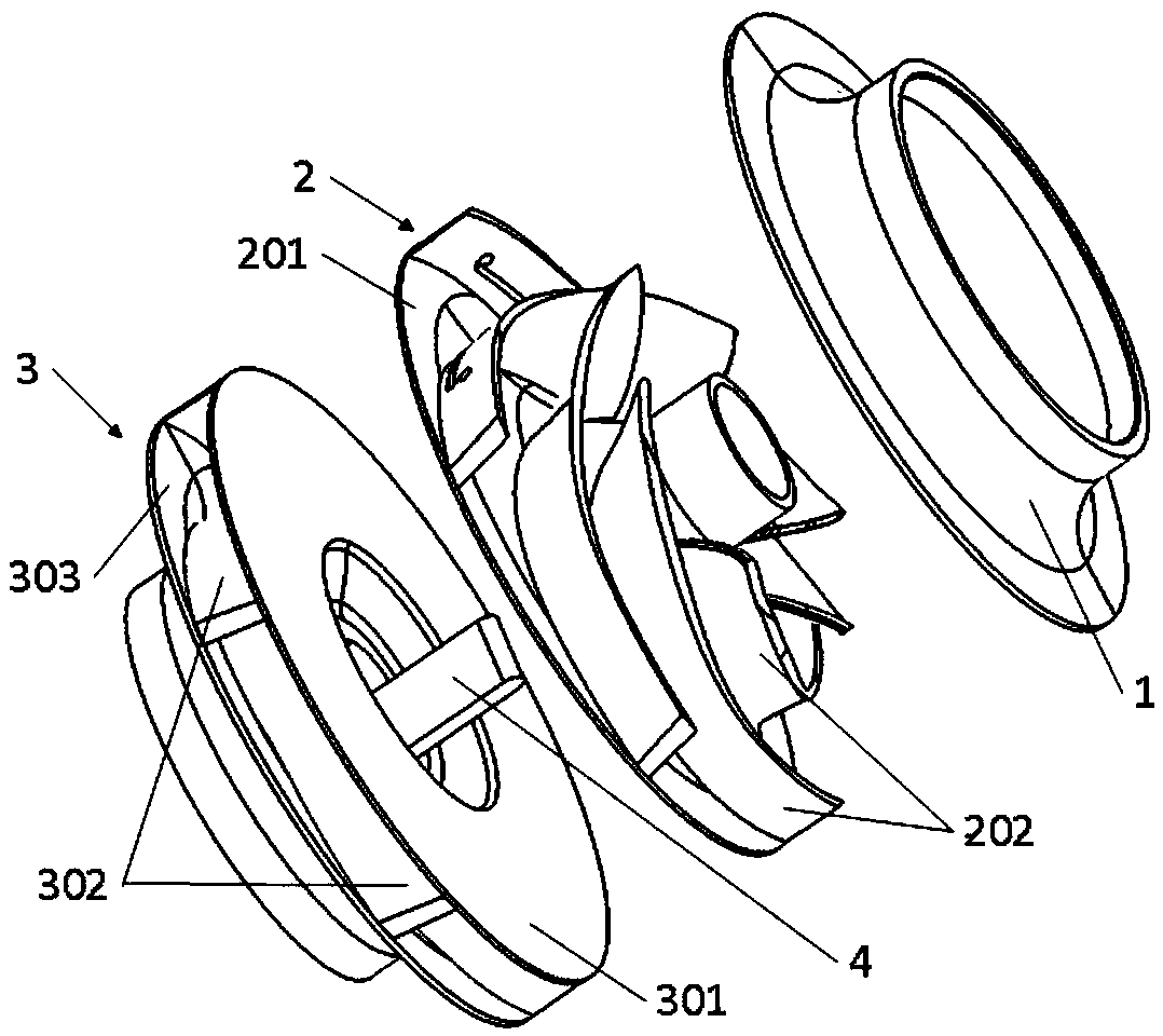
[0034] The centrifugal pump provided in this embodiment is a double-suction centrifugal pump, including the impeller described in Embodiment 1, namely figure 1 The right half of the impeller shown in , called the first impeller, also includes figure 1 The left half impeller shown in is called the second impeller 3. The structure of the second impeller 3 is basically similar to that of the first impeller, except that the second impeller 3 is processed by integral casting, that is, the blade and the end cover 1 are integrally processe...

Embodiment 3

[0037] An embodiment of the present invention also provides a centrifugal pump, including the above-mentioned impeller for measuring the pressure pulsation of the blades of the centrifugal pump. The centrifugal pump can be a double-suction pump, adopting two identical above-mentioned impellers, and the two dividing plates of the impellers are installed oppositely, or only one above-mentioned impeller can be used, such as being made into a single-suction centrifugal pump.

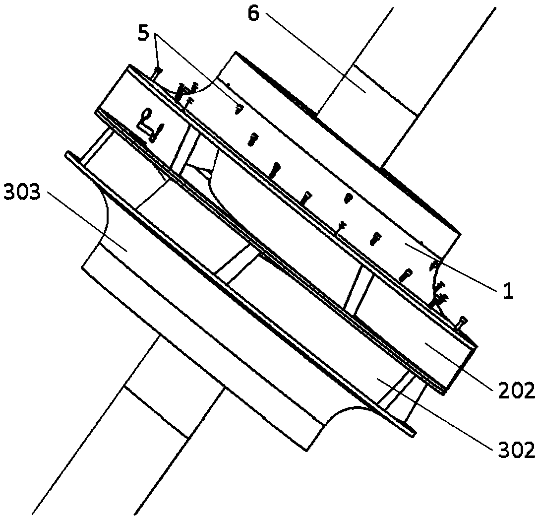
[0038] Wherein, it also includes a second pump shaft 6, the impeller is sleeved on the second pump shaft 6, the second pump shaft 6 is provided with a shaft hole 602, and the side wall of the second pump shaft 6 is provided with the shaft hole 602 Connected radial holes.


PUM


Abstract

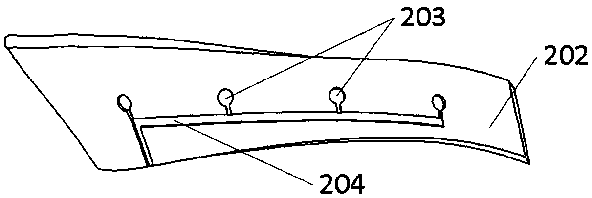
The invention relates to the field of centrifugal pump blade pressure measurement and discloses an impeller convenient to measure centrifugal pump blade pressure pulses and a centrifugal pump. The impeller comprises a clapboard, an end cover and a plurality of blades; the multiple blades are clamped between the clapboard and the end cover, the multiple blades and the clapboard are of an integrated structure, and the end cover and the blades are detachably connected; adjacent blades form flow channels, and the opposite faces of the two blades forming the corresponding flowing channel are both provided with grooves for storing sensors and wire grooves for storing leading wires; and the clapboard is provided with threading holes communicating with the wire grooves. By means of the impeller and the centrifugal pump adopting the impeller, the blade surface pressure pulses are measured while the problem of wiring of the sensors and the leading wires is also solved, influences on a flow field of the sensors and the leading wires are lowered to the minimum, and measurement precision of pulse pressure is guaranteed.

Description

technical field [0001] The invention relates to the field of measuring the blade pressure of a centrifugal pump, in particular to a centrifugal pump and an impeller for conveniently measuring the pressure pulsation of the blade of the centrifugal pump. Background technique [0002] Centrifugal pumps are often accompanied by pressure pulsations during operation, and the frequency components of pressure pulsations near the blade outlet are relatively complex, and the pulsation amplitude is large, which is one of the important factors affecting the stable operation of the impeller. Therefore, it is very important to perform a stability analysis of the impeller pressure fluctuations during the test phase of the pump. [0003] In the prior art, the measurement of the pressure pulsation on the blades can only be realized on single-suction centrifugal pumps with high specific speed and large diameter and large water turbines. For double-suction centrifugal pumps, due to the relati...

Claims


Application Information

Patent Timeline
Patent Type & Authority Patents(China)
IPC IPC(8): F04D29/22F04D29/24F04D29/043
CPCF04D29/043F04D29/185F04D29/22F04D29/242
Inventor 肖若富高贵姚志峰王福军曾永顺
Owner CHINA AGRI UNIV
Learn More